Metal structure compatible with mri imaging, and method of manufacturing such a structure

Inactive Publication Date: 2006-08-03
CR BARD INC
View PDF48 Cites 75 Cited by
  • Summary
  • Abstract
  • Description
  • Claims
  • Application Information

AI Technical Summary

Benefits of technology

[0023] It is an object of the present invention to provide a tubular metal structure, such as a stent, which allows MRI-imaging of the lumen within the tubular metal structure. It is als

Problems solved by technology

Attempts to MRI-image the blood flow and tissue-ingrowth in the vicinity of a metallic vascular implant are frustrated, or at least impaired, by the ferromagnetic or paramagnetic characteristics of the materials of the implant, which result in artefacts in the images, which reduce the quality of these images down to levels too low to be useful.
On the one hand, these artefacts are thought to be due to differences in susceptibility between metal and tissue resulting in magnetic fields in proximity of the metallic implant being non-uniform and multidirectional, thus destroying the signal respon

Method used


Image

  • Metal structure compatible with mri imaging, and method of manufacturing such a structure
  • Metal structure compatible with mri imaging, and method of manufacturing such a structure
  • Metal structure compatible with mri imaging, and method of manufacturing such a structure

Examples


Example

[0050] Skilled readers will appreciate that the stent cylinder can be formed from seamless tubular material, or from flat sheet material rolled into a seamed tube.

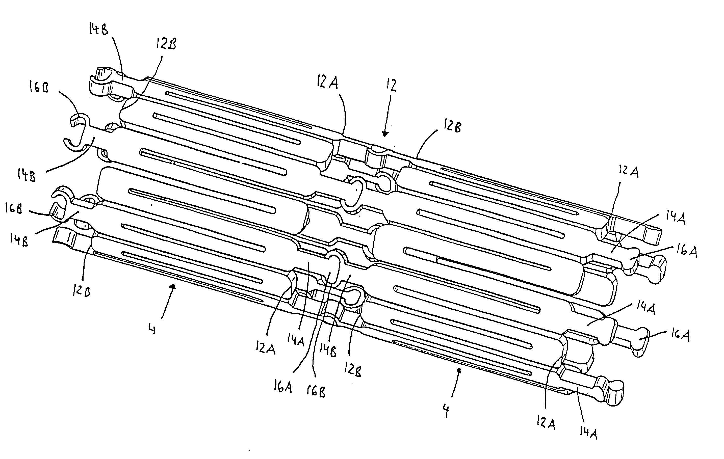
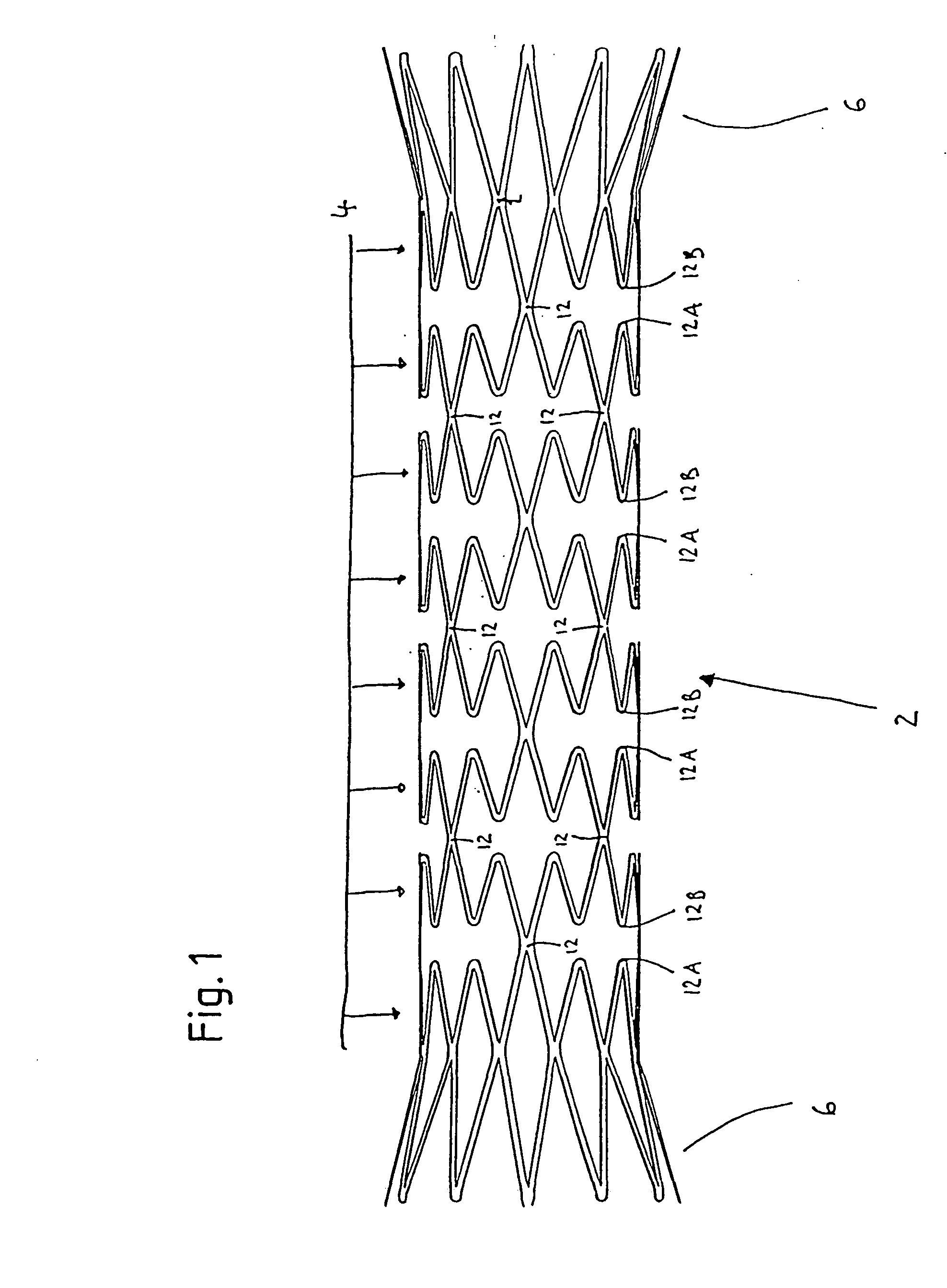
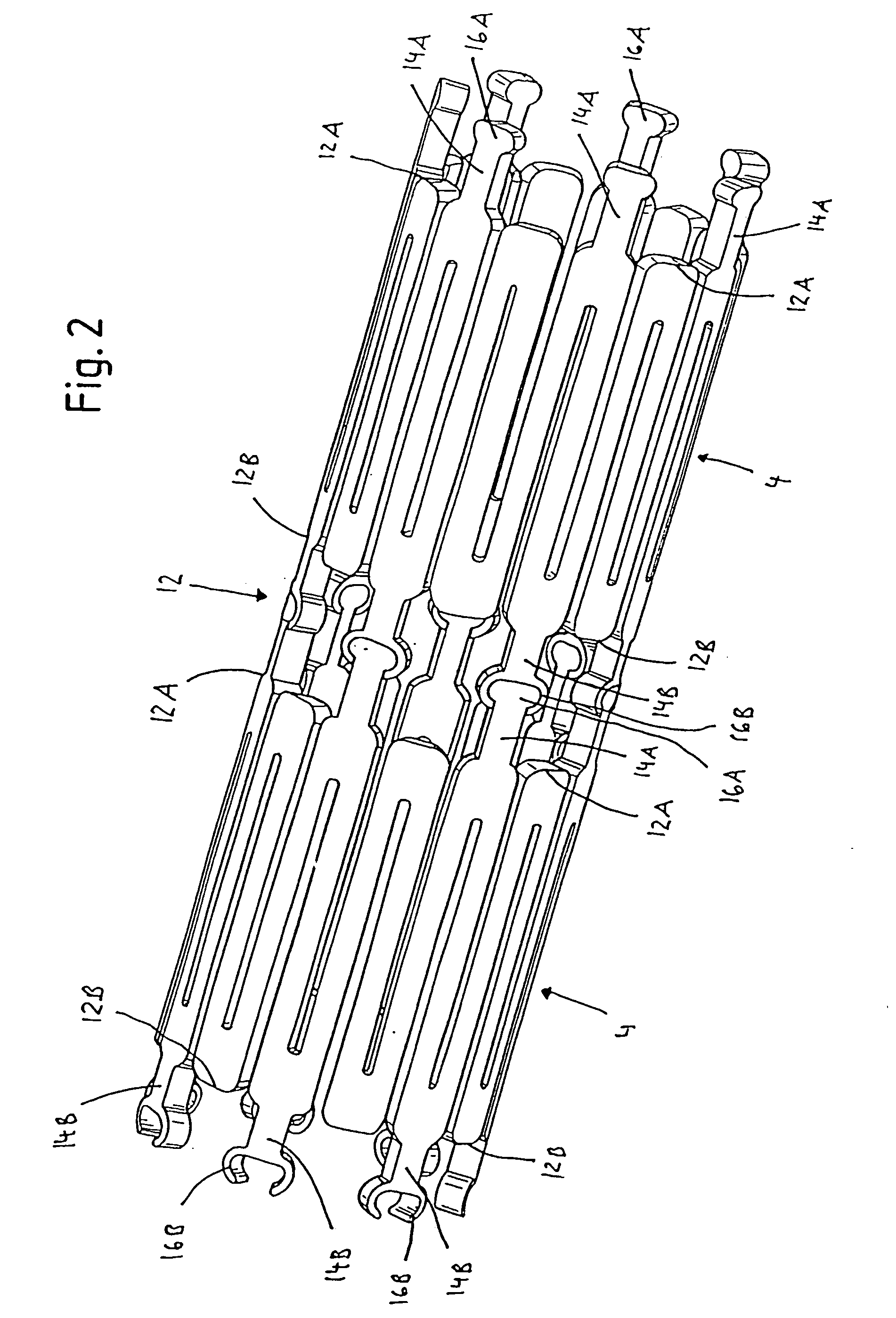
[0051] Skilled readers will also be well aware that there have been a very large number of proposals for strut patterns in the tubular configurations of stents. Whereas FIG. 1 shows an expandable strut pattern in a form which is particularly preferred for the present invention, nevertheless any of the well known strut patterns will have points at intermediate portions of the stent cylinder where individual adjacent meander-shaped rings can be attached to one another.

[0052]FIG. 1 shows a stent cylinder in the large radius configuration. As can be seen in FIG. 1, the stent cylinder 2 is constituted by a succession of struts which zig-zag their way around the full circumference of each individual ring 4. There is a vertex 12A, 12B where two successive struts intersect, and at some of which adjacent meander-shaped rings 4 ar...


PUM


Abstract

The present invention relates to tubular radially expansible metal structures, having an abluminal wall, a luminal wall and a radial wall thickness therebetween with struts defining through-apertures in the wall, the structure further defining a plurality of expansible rings arranged adjacent one another along the longitudinal axis of the structure, each of the rings defining at least one bridge strut, and adjacent rings being linked by a bridge extending between adjacent bridge struts on adjacent rings. The bridges, a plurality of which are distributed throughout the length of the tubular structure and are configured and arranged to divide the tubular structure into axially spaced and electrically insulated sections, advantageously exhibit reduced electrical conductivity throughout their wall thickness. The present invention relates furthermore to a method of manufacturing such a tubular structure, as well as a method of visualizing a bodily lumen supported by such a tubular structure deployed therein.

Description

FIELD OF THE INVENTION [0001] This invention relates to magnetic resonance imaging of a metal structure, and in particular, but not exclusively, to a tubular radially expansible metal structure, and in particular to such a tubular metal structure which defines a plurality of expansible rings arranged adjacent one another along the longitudinal axis of the structure, and in which each of the rings defines at least one bridge end and adjacent rings being linked by a bridge extending between adjacent bridge ends on adjacent rings. The invention also relates to a method of manufacturing such a tubular metal structure, and to a method of visualising a lumen supported by such a tubular metal structure using a MRI-technique. [0002] The present invention has particular usefulness for providing tubular structures in the form of medical stents, irrespective of whether they are self-expandable or balloon-expandable, made of a surgical grade material, such stainless steel, cobalt or nickel-tita...

Claims


Application Information

Patent Timeline
IPC IPC(8): A61F2/06G01R33/28A61B5/055A61F2/00A61F2/82A61F2/84A61F2/89A61F2/90A61F2/91A61F2/915
CPCA61F2/91A61F2/915A61F2002/828A61F2002/91525A61F2002/91541A61F2002/91558A61F2002/91591A61F2250/0039A61F2/89A61F2230/0054
Inventor BLANK, THIEMO ARNIM
Owner CR BARD INC
Why Eureka
Try Eureka