Swimming pool cleaning device

a cleaning device and swimming pool technology, applied in the direction of cleaning process, cleaning apparatus, brushes, etc., can solve the problems of ineffective removal of limestone by the operator, difficulty in removing limestone and rust, and ineffective cleaning of conventional cleaning machines, etc., to achieve the effect of reducing or eliminating the abov

Active Publication Date: 2006-08-10
PARETI VITTORIO
View PDF8 Cites 96 Cited by
  • Summary
  • Abstract
  • Description
  • Claims
  • Application Information

AI Technical Summary

Benefits of technology

[0011] The main object of the present invention is to provide a swimming pool cleaning device that is capable of eliminating or substantially reducing the above mentioned drawbacks and problems.
[0012] Another object of the present invention is to provide a cleaning device having improved ability of removing scaling, such as limestone, rust, sludge and weeds with respect to cleaning machines of conventional type.
[0013] Another object of the present invention is to provide a swimming pool cleaning machine that is much safer than conventional cleaning machines against any drawbacks due to the presence of a cable designed to supply electric current to a cleaning machine immersed in the water of a swimming pool.
[0014] Another object of the present invention is to provide a swimming pool cleaning machine that is not subjected to be frequently stopped for filter maintenance.
[0015] A further object of the present invention is to provide a cleaning machine for swimming pools, which can be manufactured at competitive costs.

Problems solved by technology

However, cleaning machines at present available on the market have some drawbacks.
First of all, conventional cleaning machines are unable effectively to remove limestone and “rust” accrued and attached to the swimming pool walls.
Limestone and rust removal requires hard manual work by the operator, who after a cleaning operation by means of a cleaning machine has to remove manually any scales on the swimming pool walls by means of brushes and the use of chemicals.
The filtering bag is thus liable to became obstructed quite rapidly especially if leaves, wooden fragments or other polluting elements of substantial size with respect to the dimensions of the filtering bag or through openings thereof.
When limestone, rust algae and fungi are firmly attached to the swimming pool walls, the two rotary brushes of a cleaning machine are fully inadequate to insure that the swimming pool floor and walls are satisfactorily cleaned.
Moreover, the electric cable, which plunges into water from the outside of the swimming pool for supplying the cleaning machine, represents often a risk of current escape.

Method used


Image

  • Swimming pool cleaning device
  • Swimming pool cleaning device
  • Swimming pool cleaning device

Examples


Embodiment Construction

[0031] In the accompanying drawings, the same or similar parts or components have been indicated with the same reference numerals.

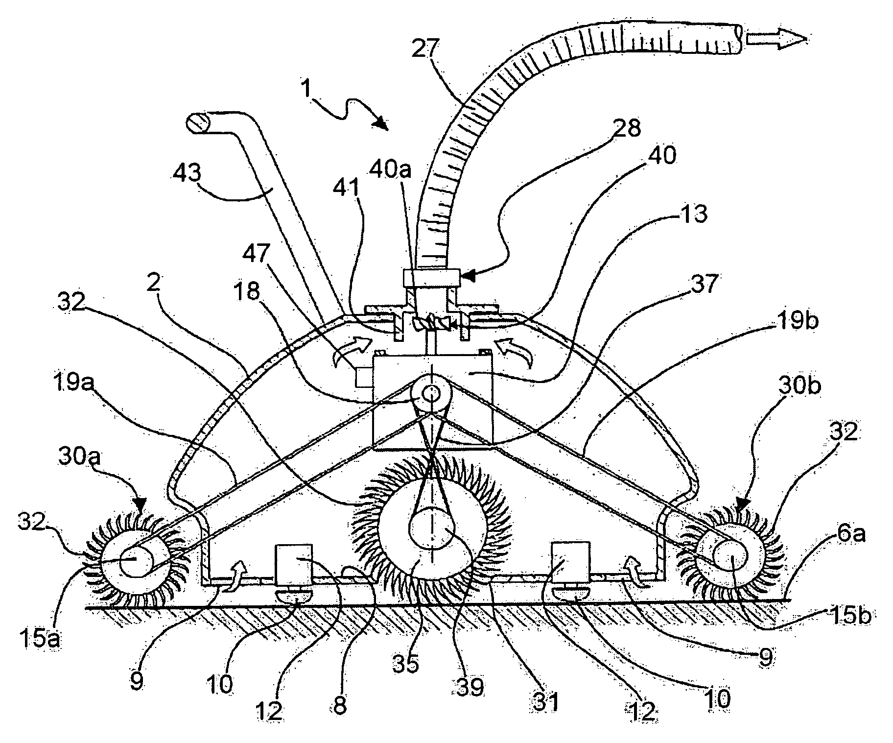
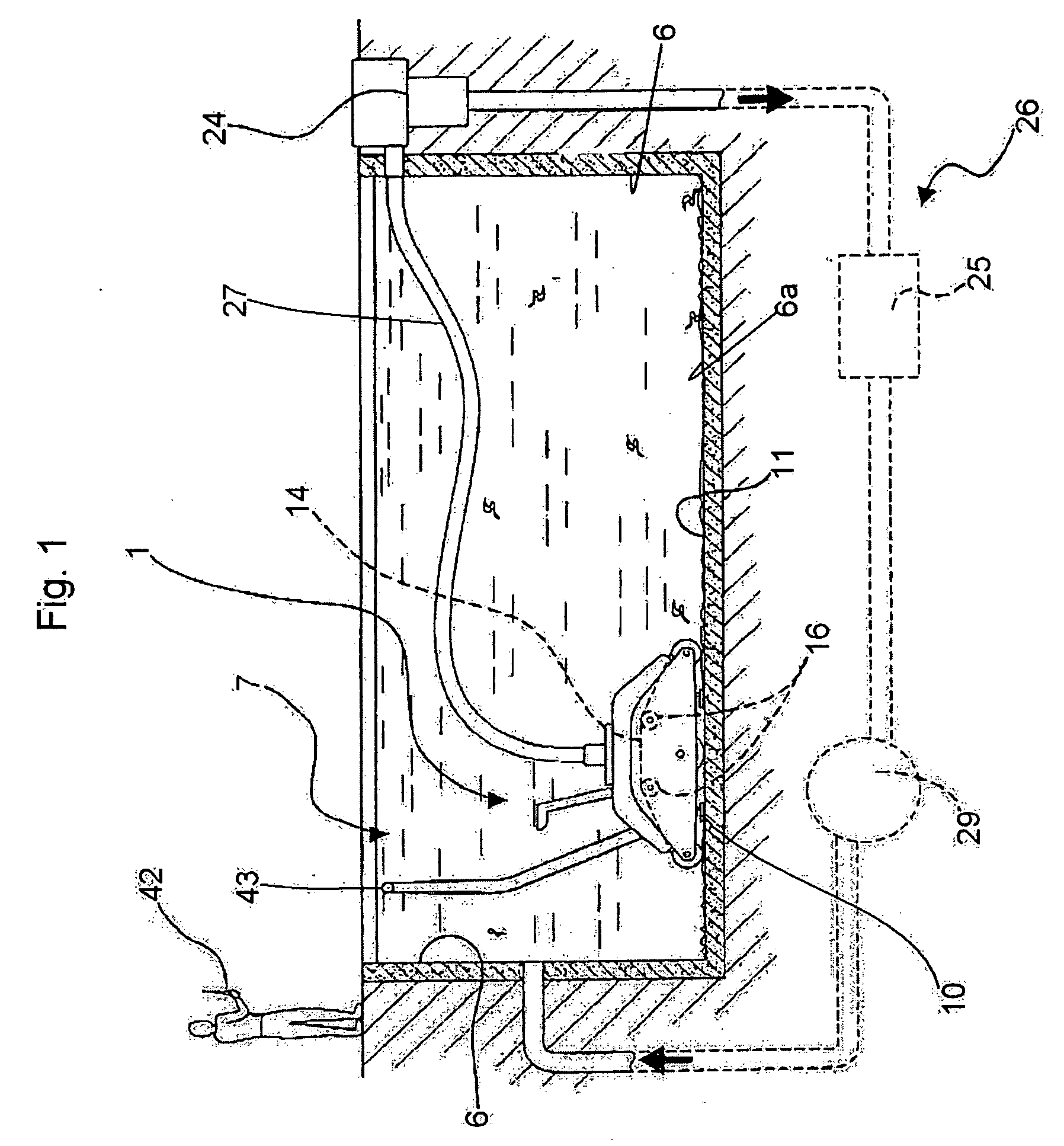
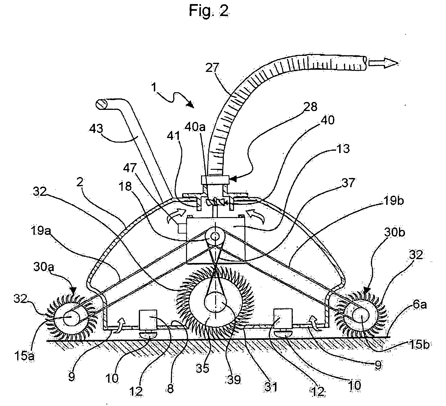
[0032] With reference first to FIGS. 1 to 5, a cleaning device according to the present invention includes a cleaning machine 1, which comprises a housing shell 2, driving means 3, e.g. a reversible electric motor arranged within the housing shell 2, a support frame 4 which is secured in position in housing shell 2, advancing means 5 that will be described in further detail below for moving the cleaning machine 1 to and fro on a side wall 6 or the bottom 6a of a swimming pool 7, said advancing means 5 being driven by the driving means 3.

[0033] The driving means 3 are hermetically enclosed (sealed) in housing shell 2 and arranged to be electrically connected to power supply means, also further described below. Preferably, the housing shell 2 has a flat bottom 8 in which one or more openings 9 are formed, swimming pool water being sucked, in use, through ...


PUM


Abstract

The present invention relates to a swimming pool cleaning assembly comprising at least one ultrasonic generating means (10; 46b). Advantageously the swimming pool cleaning assembly comprises a swimming pool cleaning machine including a support frame (4), a housing shell (2) provided with a bottom wall (8) and arranged around the support frame (4), driving means (3) located in said housing shell (2), advancing means (5) supported by said frame (4) and arranged to be placed, in use, on a surface to be cleaned (6, 6a) of a swimming pool (7) and driven by said driving means (3), at least one water suction opening (9) provided in the bottom surface (8) of said housing shell (2), which is designed to be put in fluid communication with water suction means, said driving means (3) being tight sealed in the housing shell (2) and electrically connectable to supply means, said ultrasonic generating means (10) being arranged at said bottom wall (8) facing, in use, said surface to be cleaned (6, 6a).

Description

FIELD OF INVENTION [0001] The present invention relates to a swimming pool cleaning device. BACKGROUND OF INVENTION [0002] Swimming pool cleaning machines are known and largely adopted at present, which comprise a frame supported by driving means, e.g. an electric motor designed to drive a number of small wheels or tracks arranged to move the cleaning machine backward and forward on an inner surface of a swimming pool, and one or more inlet openings arranged to suck from the bottom of the machine, the whole assembly being arranged in a housing shell. [0003] The driving means is tight sealed in the housing shell and generally electrically connected by means of an electric cable, preferably provided with a float, to power mains through a transformer or a low-tension power supply located near to the swimming pool. [0004] Generally speaking, the electric motor also drives a pair of rotatable brushes having their axes of rotation parallel to one another and arranged at two opposite sides...

Claims


Application Information

Patent Timeline
Patent Type & Authority Applications(United States)
IPC IPC(8): E04H4/16
CPCE04H4/1654B08B1/04B08B3/12A46B13/023A46B15/0028A46B2200/3066E04H4/1672E04H4/1663
Inventor PARETI, VITTORIO
Owner PARETI VITTORIO
Why Eureka
Try Eureka