Remote humidity monitoring system

a humidity monitoring and remote technology, applied in the field of remote humidity monitoring system, can solve the problem that no humidity sensor exists in the medical/nursing field

Inactive Publication Date: 2006-08-10
THINKFAR NANOTECH CORP
View PDF6 Cites 46 Cited by
  • Summary
  • Abstract
  • Description
  • Claims
  • Application Information

AI Technical Summary

Benefits of technology

[0012] In the above-mentioned description, the humidity sensor can be a comb electrode, a mass hygrometer, an optical condensation dew-point hygrometer, a psychrometer (wet-and-dry bulb thermometer), a hair hygrometer, an electrolysis humidity sensor, a lithium chloride humidity sensor, an aluminum oxide humidity sensor, a high polymer humidity sensor, or an infrared hygrometer.

Problems solved by technology

However, no humidity sensor exists for the medical / nursing fields.

Method used


Image

  • Remote humidity monitoring system
  • Remote humidity monitoring system

Examples


first embodiment

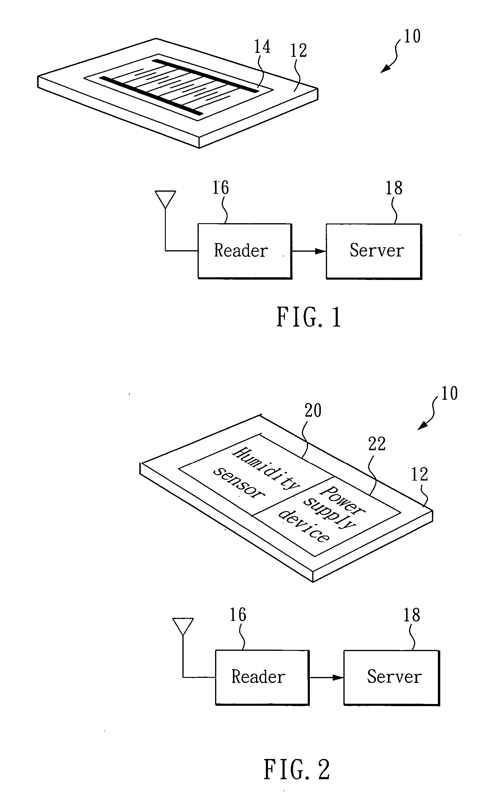
[0017] As shown in FIG. 1, a remote humidity monitoring system 10 comprises a radio frequency tag 12, a comb electrode 14, and a reader 16.

[0018] The radio frequency tag 12 is a primary element provided in RFID (radio frequency identification) systems, and can communicate with another primary element. The radio frequency tag 12 can be divided into an active radio frequency tag and a passive radio frequency tag, which are both formed from a substrate, a coil antenna and a control chip. The coil antenna and the control chip both are mounted on the substrate. The active radio frequency tag further comprises a power supply device. In this embodiment, the radio frequency tag 12 is a passive radio frequency tag to allow for reduced sizes. The coil antenna is used for receiving electromagnetic pulses, which excite the coil antenna to generate power for the control chip; the control chip then causes the coil antenna to transmit a radio frequency signal to a far end. To enhance the humidity...

second embodiment

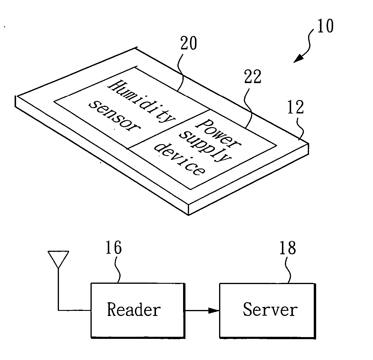
[0021] As shown in FIG. 2, a remote humidity monitoring system 10 comprises a radio frequency tag 12, a humidity sensor 20, a power supply device 22, and a reader 16.

[0022] The humidity sensor 20 can be a mass hygrometer, an optical condensation dew-point hygrometer, a psychrometer (wet-and-dry bulb thermometer), a hair hygrometer, an electrolysis humidity sensor, a lithium chloride humidity sensor, an aluminum oxide humidity sensor, a high polymer humidity sensor, or an infrared hygrometer. The humidity sensor 20 is used to detect the current humidity and outputs a humidity value to the control chip of the radio frequency tag 12.

[0023] The radio frequency tag 12, in this embodiment, is preferably a radio frequency tag. The control chip can input a humidity value and perform a modulation process to generate a radio frequency signal. The control chip then outputs the radio frequency signal, which encodes the humidity value, to the coil antenna. Further reference may be made to the ...


PUM

PropertyMeasurementUnit
humidityaaaaaaaaaa
radio frequencyaaaaaaaaaa
impedanceaaaaaaaaaa

Abstract

A remote humidity monitor system for detecting a targeted object utilizes a humidity sensor to detect humidity and sends a result to a reader via the wireless communication device; a server can execute monitor management. The humidity sensor can be a mass hygrometer, an optical condensation dew-point hygrometer, a psychrometer (wet-and-dry bulb thermometer), a hair hygrometer, an electrolysis humidity sensor, a lithium chloride humidity sensor, an aluminum oxide humidity sensor, a high polymer humidity sensor, or an infrared hygrometer.

Description

BACKGROUND OF THE INVENTION [0001] 1. Field of the Invention [0002] The present invention relates to a remote humidity monitoring system. [0003] 2. Description of the Related Art [0004] There are various high-level humidity sensors, such as: mass hygrometers, optical condensation dew-point hygrometers, psychrometers (wet-and-dry bulb thermometers), hair hygrometers, electrolysis humidity sensors, lithium chloride humidity sensors, aluminum oxide humidity sensors, high polymer humidity sensors, or infrared hygrometers. All these humidity sensors can be divided into different types, such as impedance type, capacitance type and other types, according to their theory of operation. The impedance-type humidity sensors utilize organic sensing materials and inorganic sensing materials. Macromolecule organic sensing materials include ammonia, esters, alcohols, etc. Inorganic sensing materials have greater stability than the organic sensing materials, and higher sensitivities in low humidity ...

Claims


Application Information

Patent Timeline
Patent Type & Authority Applications(United States)
IPC IPC(8): G01N7/00G08B21/00
CPCA61F13/42
Inventor CHEN, CHEI-CHIANGWANG, PO-YENCHIEN, JUI-HUNG
Owner THINKFAR NANOTECH CORP
Why Eureka
Try Eureka