Apparatus and method for heating fluids

a technology of liquid heating and apparatus, applied in the direction of heating fuel, steam generation using mechanical energy, other heat production devices, etc., can solve the problem that the giggs machine would take a long time to reach steady state conditions before reaching maximum efficiency, and achieve the effect of reducing the risk of bearing and seal failur

a technology of liquid heating and apparatus, applied in the direction of heating fuel, steam generation using mechanical energy, other heat production devices, etc., can solve the problem that the giggs machine would take a long time to reach steady state conditions before reaching maximum efficiency, and achieve the effect of reducing the risk of bearing and seal failur

US20060174845A1Inactive Publication Date: 2006-08-10THOMA CHRISTIAN HELMUT

Image

  • Apparatus and method for heating fluids
  • Apparatus and method for heating fluids
  • Apparatus and method for heating fluids

Examples


Embodiment Construction

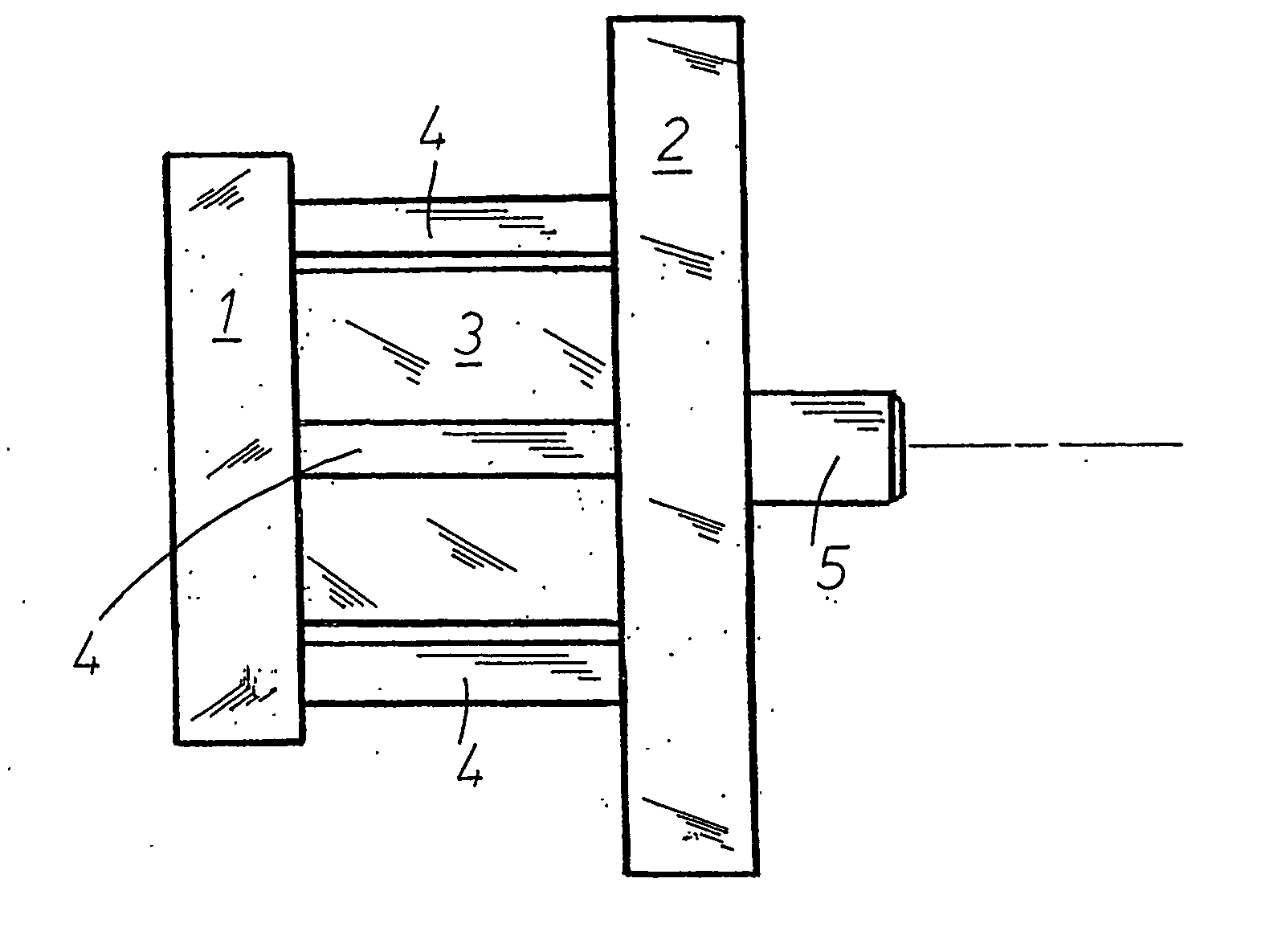
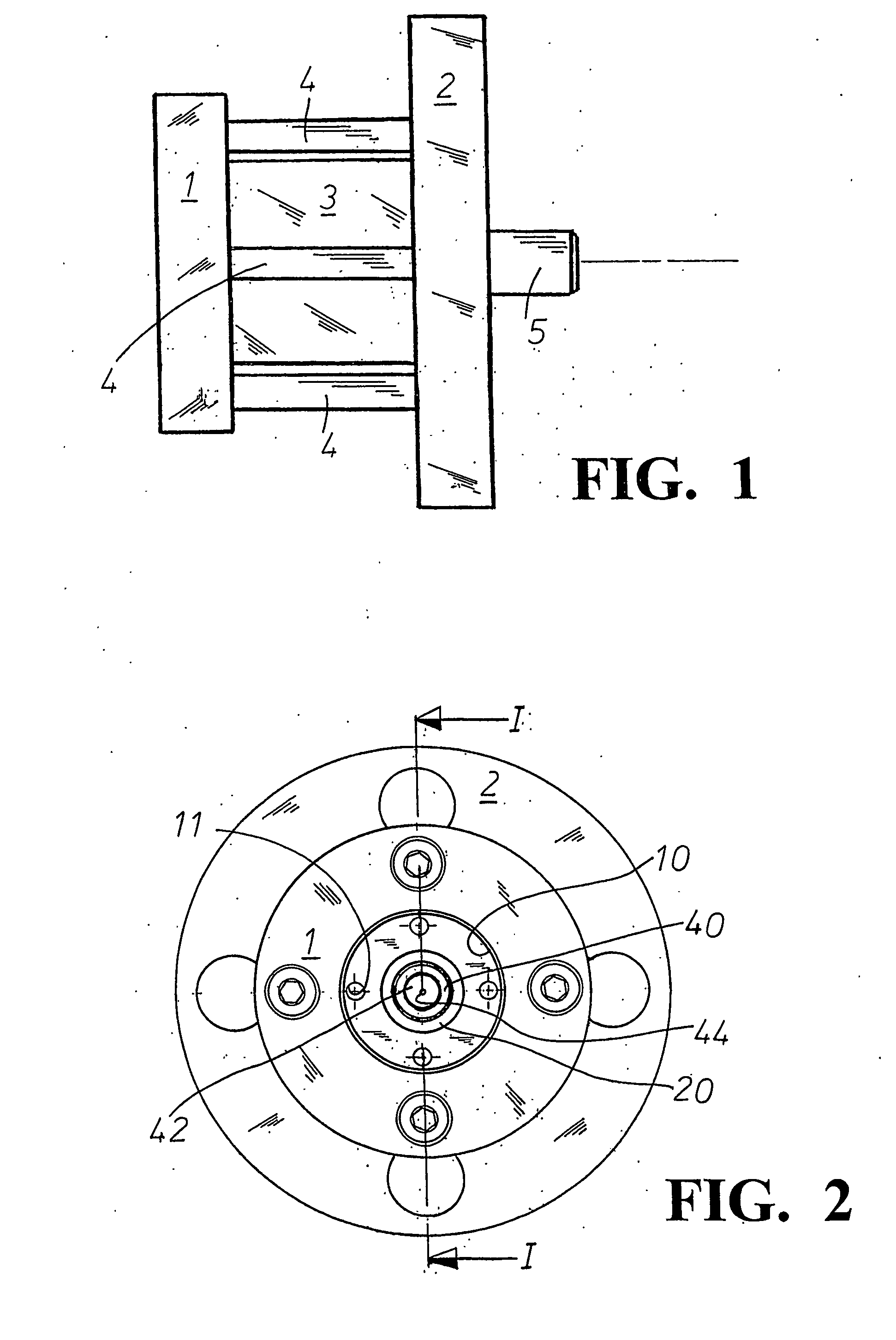
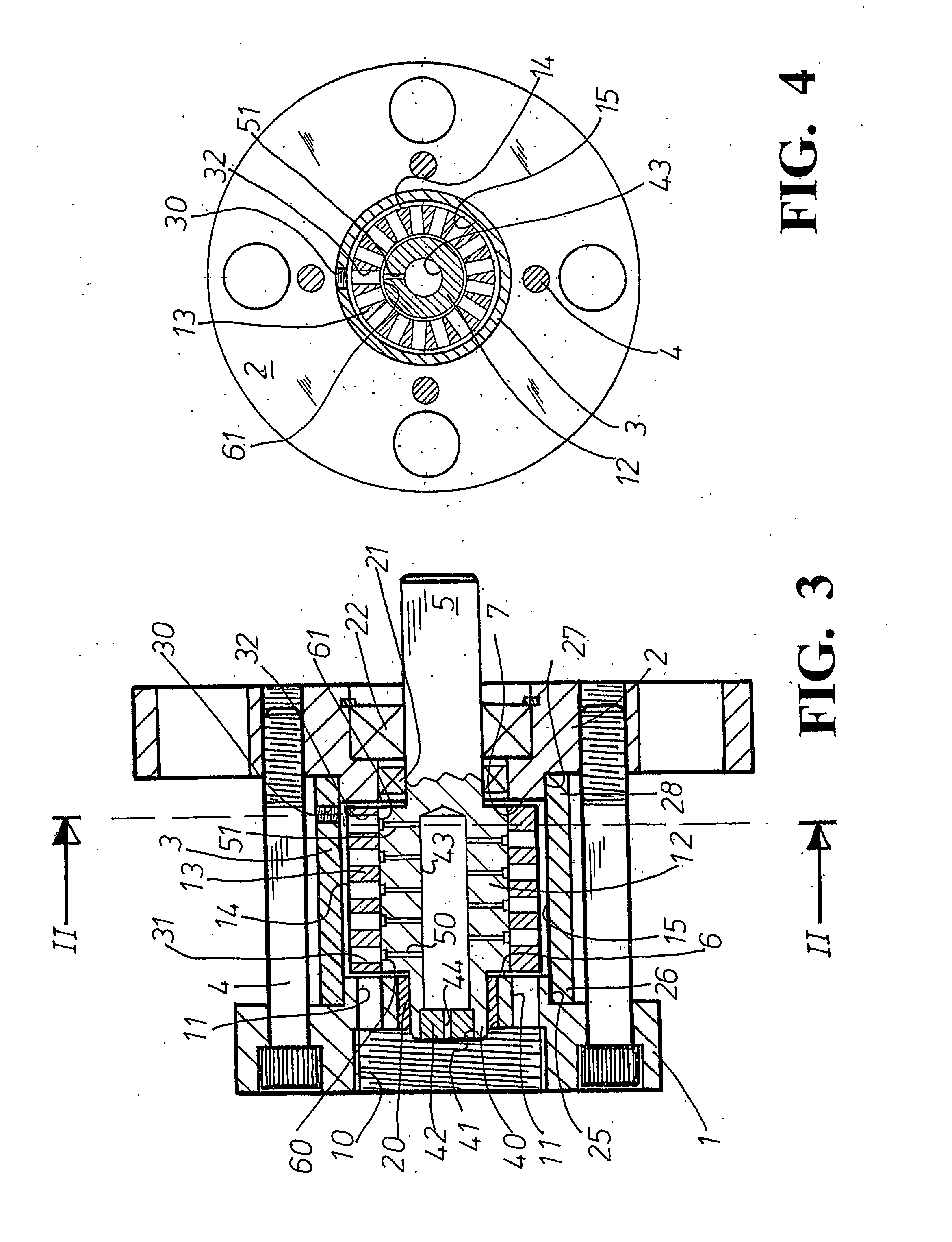
[0050] Referring to FIGS. 1 to 4, the device shows a housing structure comprising rear housing member 1, front housing member 2 and a tubular central housing member 3. Housing member 3 with bore 15 is a sleeve which spans across from end face 6 of rear housing member 1 to the face 7 of the front housing member 2 and the space inside is the main chamber of the device. Four screws 4 are arranged to engage members 1, 2 with member 3 thereby sandwiched in-between. Drive shaft 5 is shown protruding out from front housing member 2 in FIG. 1. The rear view of housing member 1 in FIG. 2 shows threaded fluid intake connection 10, also called the “inlet” or “intake”, and well as fluid ports 11 which become more clearly depicted with reference to FIG. 3. The inlet 10 is shown rather large in diameter in order for access to be obtained for a drill in order that fluid ports 11 can be created, the ports 11 fluidly communicate inlet 10 with the end face 6 of the rear housing member 1. In later emb...


PUM


Abstract

An apparatus for heating a liquid includes a housing having an internal chamber and a rotor disposed in the chamber. The rotor is preferably cylindrical and operates inside a bore provided by the housing without touching, the shape of the bore preferably being parallel with the exterior surface of the rotor, and a series of openings disposed over the rotor surface. At least one internal passageway in the rotor and elements for: pre-heating some or all the incoming fluid in the chamber; priming the chamber initially; cooling certain temperature sensitive components; injecting fluid into a partially evacuated volume; developing a vacuum state during operation expeditiously.

Description

BACKGROUND OF THE INVENTION [0001] The invention relates generally to the heating of liquids, and specifically to those devices wherein rotating elements are employed to +generate heat in the liquid passing through them. Devices of this type can be usefully employed in applications requiring a hot water supply, for instance in the home, or by incorporation within a heating system adapted to heat air in a building residence. Furthermore, an economic portable steam generator could be useful for domestic applications such as the removal of winter salt from the underside of vehicles, or the cleaning of fungal coated paving stones in place of the more erosive method by high-pressure water jet. [0002] Of the various configurations that have been tried in the past, types employing rotors or other rotating members are known, one being the Perkins liquid heating apparatus disclosed in U.S. Pat. No. 4,424,797. Perkins employs a rotating cylindrical rotor inside a static housing and where flui...

Claims


Application Information

Patent Timeline
10 Aug 2006
Publication
US20060174845A1
IPC
F22B3/06
CPC
F22B3/06; F24J3/006; F24V40/10
Inventors
THOMA, CHRISTIAN HELMUT