Compact backwashable water filter system

Inactive Publication Date: 2006-08-10
GREENE WILLIAM A
View PDF9 Cites 14 Cited by
  • Summary
  • Abstract
  • Description
  • Claims
  • Application Information

AI Technical Summary

Benefits of technology

[0003] In accordance with one embodiment of the invention, a water filter system is provided that is of simple construction and that is self cleaning. The system includes a valve structure that can carry pressured feed water such as from a municipal water supply, to a passage containing a bidirectional filter arrangement such as hollow fibers with microscopic pores. The water flows forward through the hollow fibers to an outlet storage region from which water can be drawn to flow to a faucet, nozzle or other flow control. A water pressurizing device, such as a bladder having one side facing the water outlet storage region and an opposite side facing a pressured air chamber, maintains water in the outlet storage region under pressure. At intervals such as every 24 hours, in the middle of the night, a timer operates the valve structure to open a connection to a drain, for a period such as 20 seconds. Then, water in the outlet storage region is moved by the bladder in a reverse or backward direction though the bidirectional filter elements to the drain. This results in a backwashing of the filter elements and of the passage, to eliminate debris, which may include bacteria, that has accumulated on the filter elements and in the passage. The filter elements are preferably small diameter porous plastic tubes with very small pores or with a coating of a filtering layer such as polysulfone.
[0005] In another system, backflushing is enhanced by allowing pressured feed water to flow across the outside of the fibers while filtered water in the outlet storage region flows backward through the fibers to their outer surfaces to clean the pores in the fibers. The filtered water that has cleaned the fiber pores then flow out with the pressured feed water to the drain.

Problems solved by technology

The output of water from the system is then limited by the flow rate of water though the filtering elements.

Method used


Image

  • Compact backwashable water filter system
  • Compact backwashable water filter system
  • Compact backwashable water filter system

Examples


Embodiment Construction

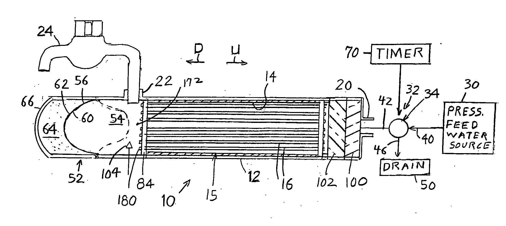
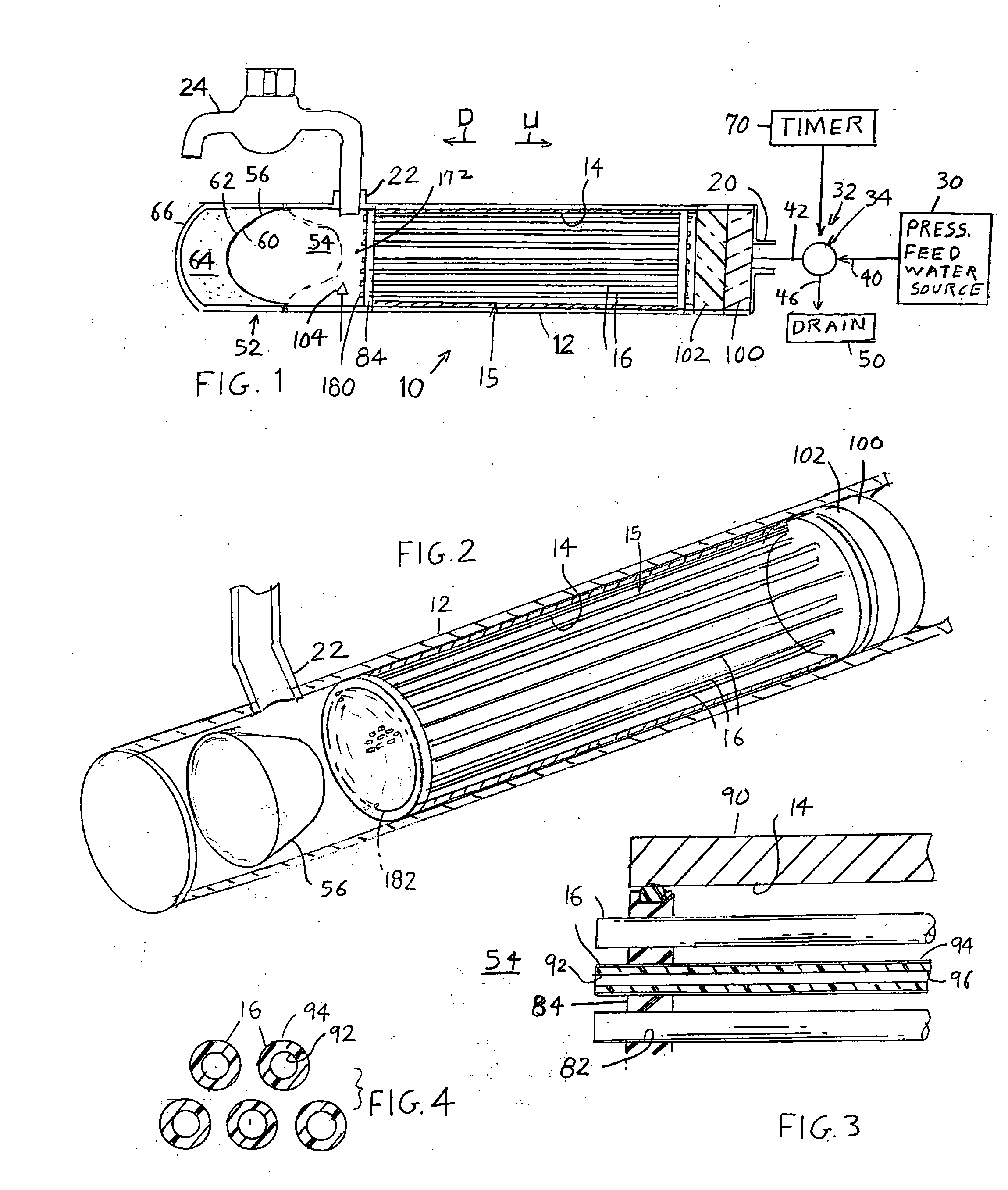
[0014]FIGS. 1-4 illustrate a water filter system 10 for home, office, or the like which includes a conduit 12 and walls forming a filter passage 14 of the conduit that surrounds a filter arrangement 15 that includes a plurality of filter elements 16, such as tubular filters. The conduit has an inlet 20 that receives feed water to be filtered and has an outlet 22 for dispensing filtered water. The outlet is shown connected to a faucet 24 such as a household faucet that dispenses water for drinking or cooking. Feed water is received from a pressured feed water source 30 such as a municipal water system. The water flows though a valve structure 32 formed by a three-way valve 34 (or two 2-way valves). In the usual mode of operation, but with the faucet closed, the pressure of the feed water is maintained throughout the passage 14 but there is no water flow. In the usual mode of operation, but with the faucet opened so outflow from the outlet is unobstructed, feed water flows from a feed...


PUM

PropertyMeasurementUnit
Fractionaaaaaaaaaa
Timeaaaaaaaaaa
Timeaaaaaaaaaa

Abstract

A water filter system (10) for home use, includes a valve (34) that passes pressured water from a municipal water supply (30) though the inlet (20) of a passage (14) containing bidirectional filter elements (16) so the water has to pass though the filter elements to reach an outlet (22) that leads to a faucet (24). A water pressuring device (52) such as one that includes a bladder (56), has one side that faces a water outlet storage region (54) and an opposite side that faces a pressing apparatus such as compressed air (64). At intervals such as every 24 hours at 3:00 a.m., a timer (70) operates the control valve to connect the inlet (20) to a drain (50) instead of to the municipal water supply, for a period such as 20 seconds. Then, water backflushes though the bidirectional filter elements to a drain, to clean the filter elements. An ultraviolet light (104) at the outlet storage region kills bacteria to prevent bacteria buildup in the outlet region.

Description

CROSS-REFERENCE [0001] Applicant claims priority from U.S. provisional application 60 / 648,310 filed Jan. 28, 2005.BACKGROUND OF THE INVENTION [0002] Many municipal water supplies provide water that does not taste good, that is not reliably safe to drink, or that people do not trust, and many people wish to pass water from the municipal water supply though a filter system. Presently available filter systems should be cleaned at intervals such as every day or every several days to avoid the buildup of bacteria. Some systems recommend that people clean the filters every several days and replace them at intervals , but many people do not do such cleaning or replacement on a regular basis. This can result in bacteria growing in the system that makes the water unhealthy or unsafe. A water filter system that cleaned itself at regular intervals without requiring human intervention, and that was of simple construction and used a minimum of water, would be of value. SUMMARY OF THE INVENTION [...

Claims


Application Information

Patent Timeline
IPC IPC(8): B01D29/62
CPCB01D29/66C02F1/003C02F1/32C02F2303/16C02F2307/06
Inventor GREENE, WILLIAM A.
Owner GREENE WILLIAM A
Why Eureka
Try Eureka