Enhancement of light extraction with cavity and surface modification

a technology of surface modification and light extraction, applied in the manufacture of electrode systems, electric discharge tubes/lamps, discharge tubes luminescnet screens, etc., can solve the problem that the addition of lenses on the outside of the substrate does not provide extra benefits

Active Publication Date: 2006-08-10
DOLYA HOLDCO 5 LTD
View PDF8 Cites 41 Cited by
  • Summary
  • Abstract
  • Description
  • Claims
  • Application Information

AI Technical Summary

Problems solved by technology

However, since the DBR already channels light into the forward viewing angle effectively, the addition of lenses on the outside of the substrate provides no extra benefit.

Method used


Image

  • Enhancement of light extraction with cavity and surface modification
  • Enhancement of light extraction with cavity and surface modification
  • Enhancement of light extraction with cavity and surface modification

Examples


Embodiment Construction

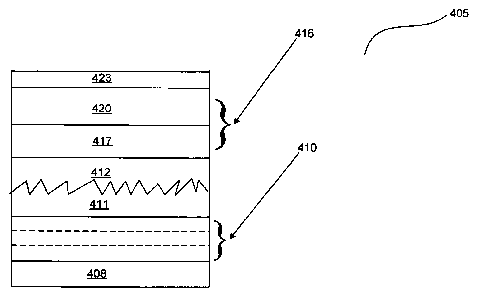
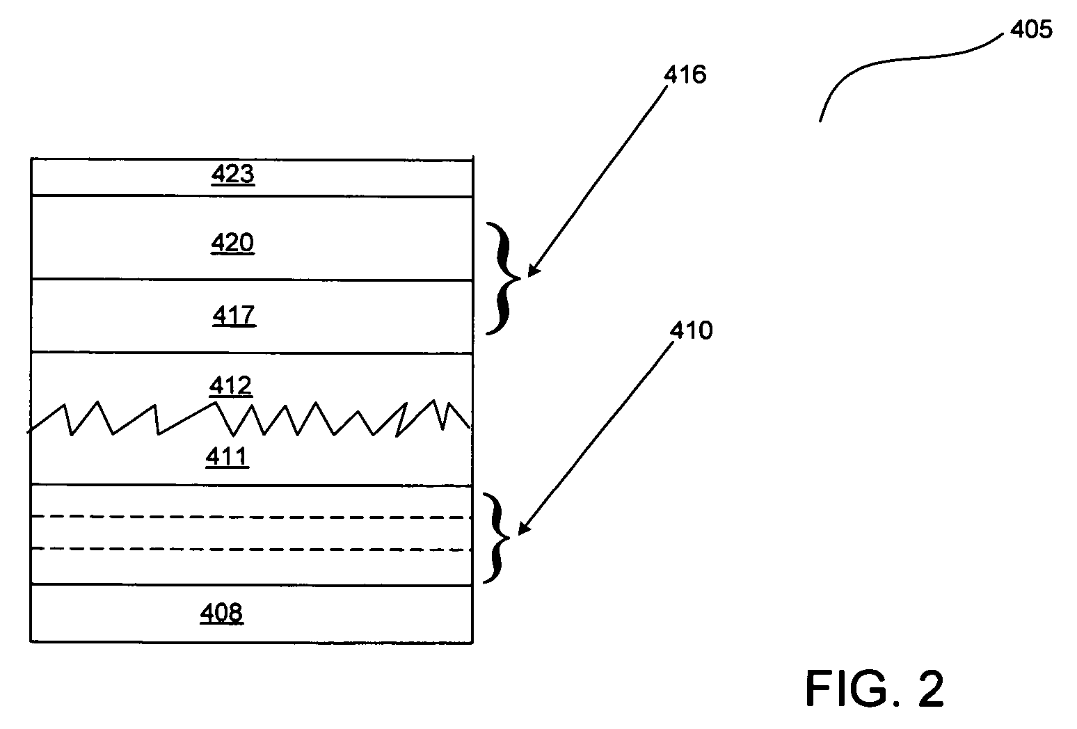
[0012] According to some embodiments of the invention, a DBR stack is utilized together with a surface modified anode layer to fabricate an OLED device. The surface modification creates lens like features on the top of the anode layer such that the angle of incidence of light from the emissive layer into the DBR stack is modified. Lens like features are defined as any feature that serves to focus / direct the light in the desired direction. It can be random or ordered, and may look like actual lenses. To maintain integrity of the organic layers of the OLED above the surface modified anode, a planarizing layer can also be provided between the surface modified anode layer and the organic layers so that a more uniform deposition surface is available for the organic layers. The surface modification of the anode layer can be accomplished by any appropriate patterning or deposition techniques such as wet-etching, lithography, e-beam lithography, stamping, or sputtering. The shape and patter...


PUM

PropertyMeasurementUnit
total thicknessaaaaaaaaaa
work functionaaaaaaaaaa
thicknessaaaaaaaaaa

Abstract

An organic light emitting diode (OLED) device includes an anode layer upon a DBR (Distributed Bragg Reflector) stack such that the anode layer is modified by creating lens-like features on its surface. The OLED device also includes a planarizing layer on said anode layer, said planarizing layer filling in said lens-like features, said planarizing layer providing a flat uniform surface for the deposition of other layers thereupon.

Description

BACKGROUND [0001] 1. Field of the Invention [0002] This invention relates generally to the art of thin film device processing and fabrication. More specifically, the invention relates to the fabrication of Organic Light Emitting Diode devices and displays. [0003] 2. Related Art [0004] Display and lighting systems based on LEDs (Light Emitting Diodes) have a variety of applications. Such display and lighting systems are designed by arranging a plurality of photo-electronic elements (“elements”) such as arrays of individual LEDs. LEDs that are based upon semiconductor technology have traditionally used inorganic materials, but recently, the organic LED (“OLED”) has come into vogue for certain lighting and display applications. Examples of other elements / devices using organic materials include organic solar cells, organic transistors, organic detectors, biochips, and organic lasers. [0005] An OLED is typically comprised of two or more thin at least partially conducting organic layers (...

Claims


Application Information

Patent Timeline
Patent Type & Authority Applications(United States)
IPC IPC(8): H05B33/00H01J1/62
CPCH01L51/5265H01L51/5275H10K50/852H10K50/858
Inventor CHOONG, VI-EN
Owner DOLYA HOLDCO 5 LTD
Why Eureka
Try Eureka