Surface-emitting laser device and surface-emitting laser array including same
a laser array and laser device technology, applied in semiconductor lasers, laser cooling arrangements, laser details, etc., can solve the problems of poor temperature characteristics, inferior output of surface-emitting laser devices in the 780 nm band, and inability to obtain high outpu
- Summary
- Abstract
- Description
- Claims
- Application Information
AI Technical Summary
Benefits of technology
Problems solved by technology
Method used
Image
Examples
first embodiment
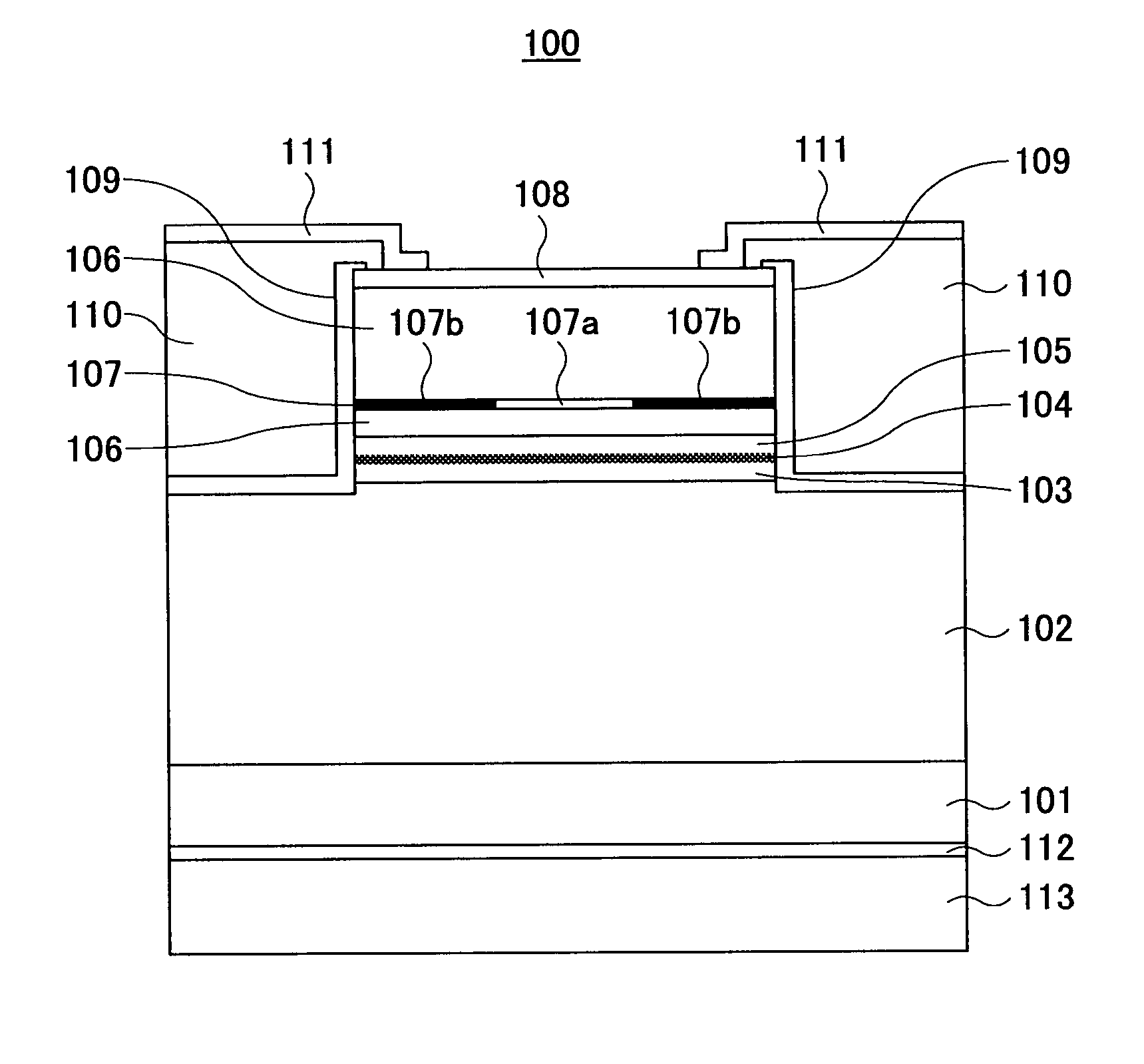
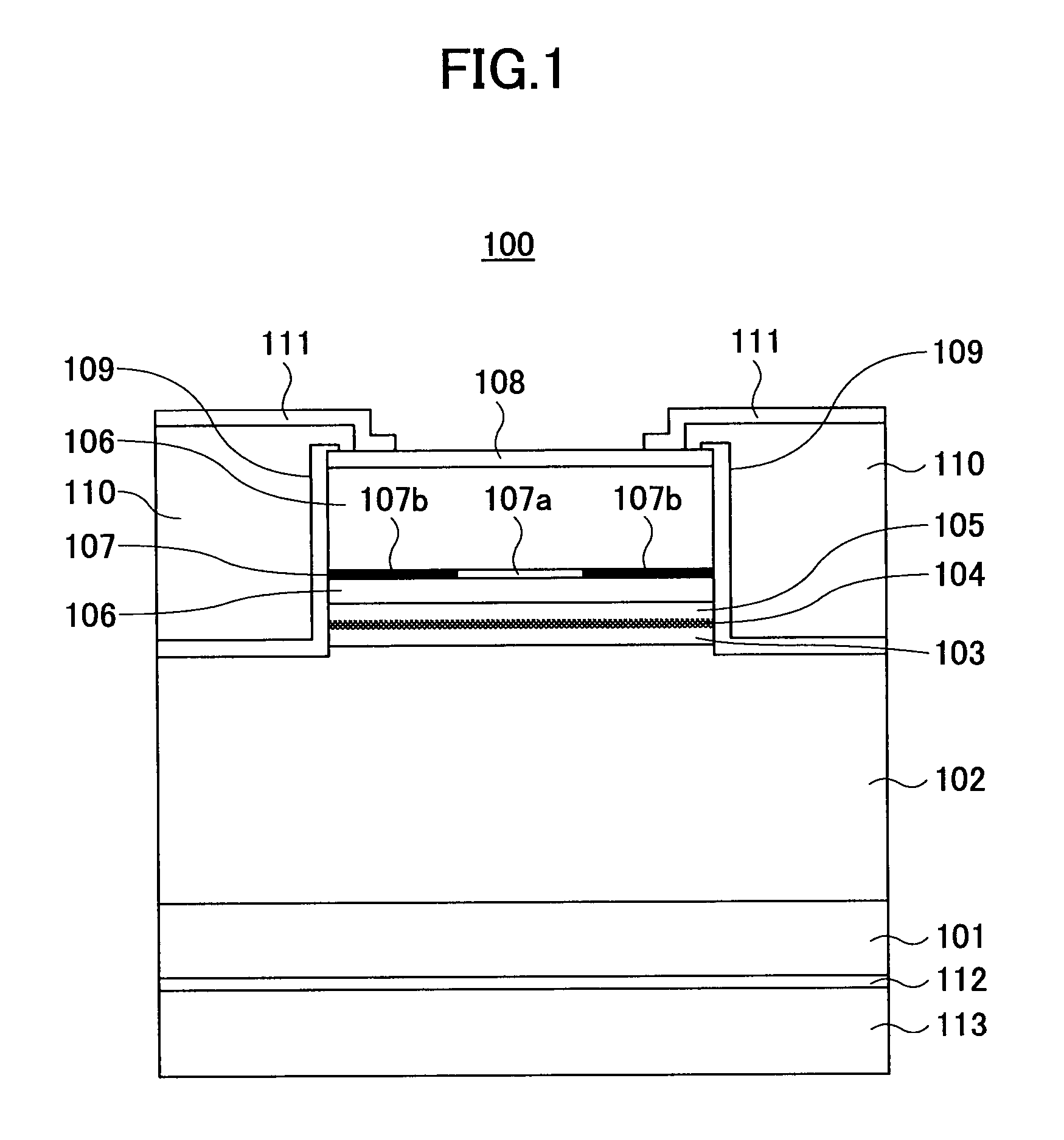
[0146]FIG. 1 is a schematic cross-sectional view of a surface-emitting laser device 100 according to a first embodiment of the present invention. Referring to FIG. 1, the surface-emitting laser device 100 includes a substrate 101, reflective layers 102 and 106, cavity spacer layers 103 and 105, an active layer 104, a selectively oxidized layer 107, a contact layer 108, a SiO2 layer 109, insulating resin 110, a p-side electrode 111, and an n-side electrode 112. The surface-emitting laser device 100 is a 780 nm band surface-emitting laser device.
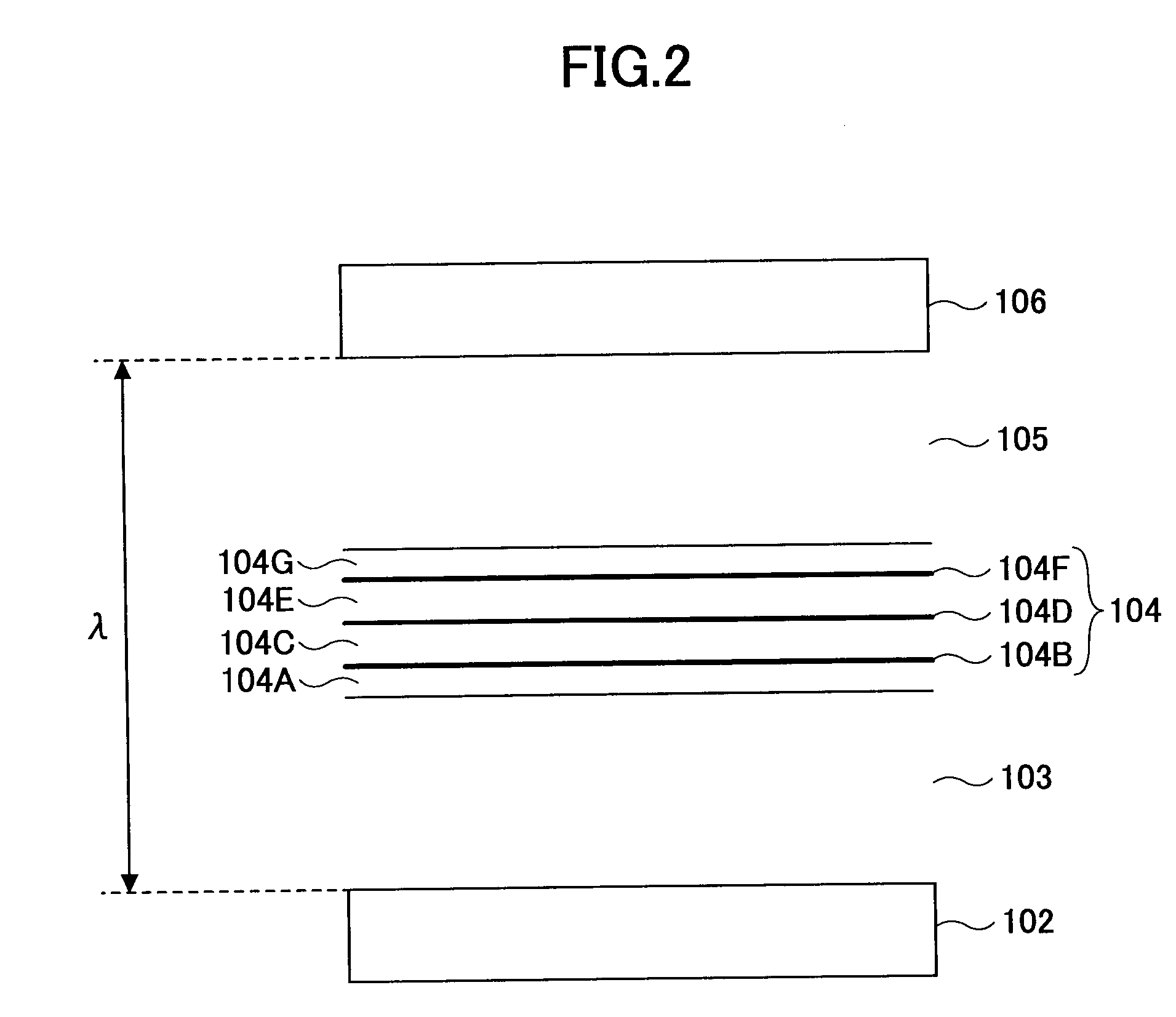
[0147] The substrate 101 is formed of (100) n-type gallium arsenide (n-GaAs) whose surface orientation is inclined at an inclination angle of 15 degrees to the direction of a (111)A surface. The reflective layer 102 is formed of 35.5 periods of [n-Al0.9Ga0.1As / n-Al0.3Ga0.7As], letting a pair of n-Al0.9Ga0.1As / n-Al0.3Ga0.7As be one period, and is formed on a principal plane of the substrate 101. Letting the oscillation wavelength of the surfac...
second embodiment
[0216]FIG. 7 is a schematic cross-sectional view of a surface-emitting laser device 100A according to a second embodiment of the present invention. Referring to FIG. 7, the surface-emitting laser device 100A is the same as the surface-emitting laser device 100 shown in FIG. 1 except that the cavity spacer layer 103 of the surface-emitting laser device 100 is replaced with a cavity spacer layer 103A.
[0217] The cavity spacer layer 103A is formed of Al0.4Ga0.6As. In the surface-emitting laser device 100A, since the cavity spacer layer 105 is formed of (Al0.7Ga0.3)0.5In0.5P, the cavity spacer layer 103A has a greater thermal conductivity than the cavity spacer layer 105. (See the curved lines k1 and k2 of FIG. 6). Thus, the surface-emitting laser device 100A has the two cavity spacer layers 103A and 105 formed of semiconductor materials asymmetrical with respect to the active layer 104, and the cavity spacer layer 103A disposed on the substrate 101 side of the active layer 104 is forme...
third embodiment
[0220]FIG. 8 is a schematic cross-sectional view of a surface-emitting laser device 100B according to a third embodiment of the present invention. Referring to FIG. 8, the surface-emitting laser device 100B is the same as the surface-emitting laser device 100 shown in FIG. 1 except that the cavity spacer layer 103 of the surface-emitting laser device 100 is replaced with a cavity spacer layer 103B.
[0221]FIG. 9 is a cross-sectional view of part of the two reflective layers 102 and 106, the two cavity spacer layers 103B and 105, and the active layer 104 shown in FIG. 8. Referring to FIG. 9, the cavity spacer layer 103B includes spacer layers 1031 and 1032. The spacer layer 1031 is formed in contact with the reflective layer 102 and the spacer layer 1032 is formed in contact with the spacer layer 1031 and the active layer 104.
[0222] The spacer layer 1031 is formed of lattice-matching Ga0.5In0.5P, and the spacer layer 1032 is formed of (Al0.7Ga0.3)0.5In0.5P.
[0223] According to the su...
PUM
 Abstract
Description
Claims
Application Information
 - R&D
- Intellectual Property
- Life Sciences
- Materials
- Tech Scout
- Unparalleled Data Quality
- Higher Quality Content
- 60% Fewer Hallucinations
Browse by: Latest US Patents, China's latest patents, Technical Efficacy Thesaurus, Application Domain, Technology Topic, Popular Technical Reports.
© 2025 PatSnap. All rights reserved.Legal|Privacy policy|Modern Slavery Act Transparency Statement|Sitemap|About US| Contact US: help@patsnap.com


