Wavelength-tunable vertical cavity surface emitting laser for swept source optical coherence tomography system

a wavelength-tunable, optical coherence tomography technology, applied in semiconductor lasers, instruments, material analysis, etc., can solve the problem that the active region and the dbr part cannot be grown on a single type substrate, and the vcsel employing a dbr composed of algainas and inp is not suitable for oct applications, etc. problem, to achieve the effect of wide tuning range, narrow dynamic line width and high axial resolution

Active Publication Date: 2015-01-08
INPHENIX
View PDF3 Cites 42 Cited by
  • Summary
  • Abstract
  • Description
  • Claims
  • Application Information

AI Technical Summary

Benefits of technology

[0014]The present invention includes a microelectromechanical system (MEMS) tunable vertical cavity surface-emitting laser (VCSEL) comprising one or more layers of quantum dots.
[0015]The present invention includes a novel MEMS tunable quantum dot-based VCSEL swept source design having a narrow dynamic line width with a wide tuning range, necessary for deeper tomographic imaging with higher axial resolution. The present invention provides a MEMS tunable quantum dot VCSEL that solves at least two problems in the prior art: (1) insufficient DBR reflectivity bandwidth of InP based DBR, and (2) complicated wafer bonding required for two different types of wafers, (as in, for example, an InP based active region wafer and a GaAs based DBR wafer). In the present invention, a GaAs based DBR with high reflection bandwidth and an active region of optical gain peak wavelength (including an exemplary embodiment centered around 1300 nm) can be epitaxially grown on a Ga

Problems solved by technology

This tuning range is not sufficient for a number of applications.
Therefore, the VCSEL employing a DBR composed of AlGaInAs and InP and an active layer comprising quantum wells is not suitable for OCT applications.
Therefore, the mat

Method used


Image

  • Wavelength-tunable vertical cavity surface emitting laser for swept source optical coherence tomography system
  • Wavelength-tunable vertical cavity surface emitting laser for swept source optical coherence tomography system
  • Wavelength-tunable vertical cavity surface emitting laser for swept source optical coherence tomography system

Examples


Embodiment Construction

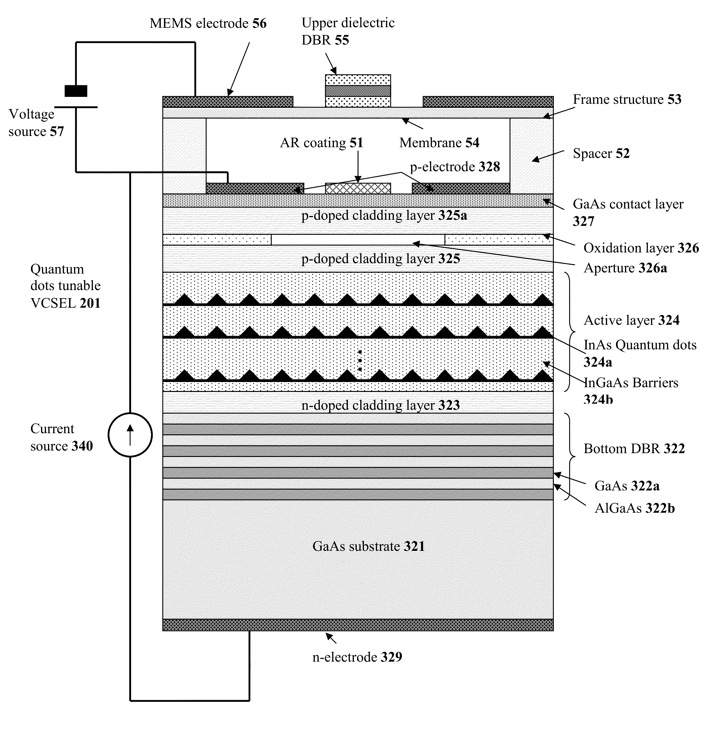
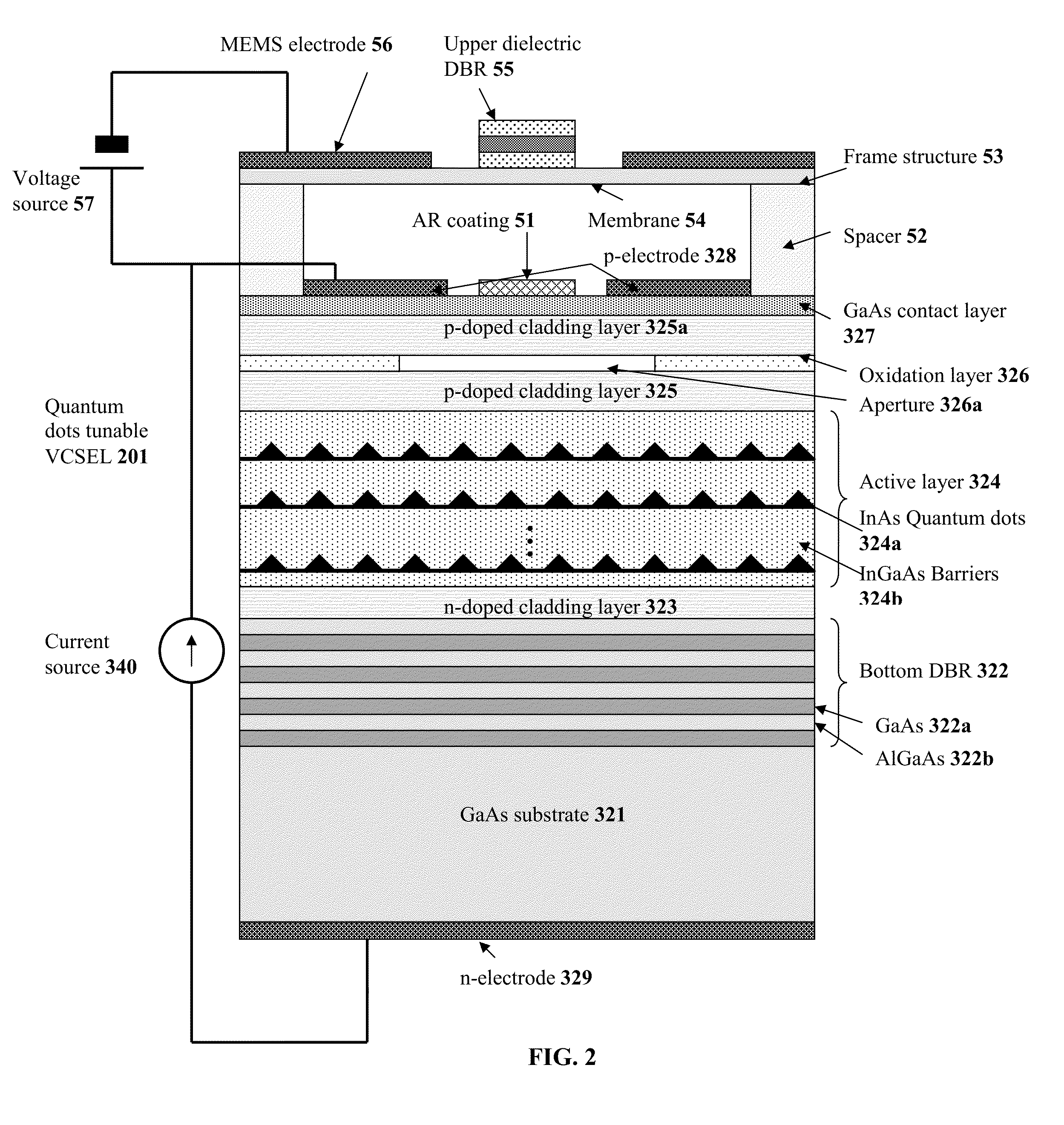
[0026]The technology of the present invention is exemplified by the two embodiments shown in FIGS. 2 and 3, respectively. Each embodiment in FIGS. 2 and 3 comprises a pair of DBR's, one in the lower VCSEL half, and one in the upper MEMS portion. The two embodiments differ in the configuration of the upper (MEMS) half of each device. Both upper portions have the same overall function, and contain a membrane, an air gap and an upper (dielectric) DBR. The laser frequency is generated from a combination of the two DBR's and the air gap in between them.

[0027]FIG. 2 shows a schematic of an exemplary embodiment of the MEMS tunable quantum dot VCSEL of the present invention. On GaAs substrate 321, a n-doped DBR 322 consisting of 30 to 40 pairs of alternating layers of GaAs 322a, and AlGaAs 322b lattice matched to GaAs, is epitaxially grown, followed by a n-doped GaAs cladding layer 323. Then, an active layer 324 consisting of multi-layer stacks of InAs quantum dots (QD's) 324a (for example,...


PUM


Abstract

A wavelength-tunable vertical-cavity surface-emitting laser (VCSEL) with the use of micro-electromechanical system (MEMS) technology is provided as a swept source for Optical Coherence Tomography (OCT). The wavelength-tunable VCSEL comprises a bottom mirror of the VCSEL, an active region, and a MEMS tunable upper mirror movable by electrostatic deflections. The bottom mirror comprising a GaAs based distributed Bragg reflector (DBR) stack, and the active region comprising multiple stacks of GaAs based quantum dot (QD) layers, are epitaxially grown on a GaAs substrate. The MEMS tunable upper mirror includes a membrane part supported by suspension beams, and an upper mirror comprising a dielectric DBR stack. The MEMS tunable quantum dots VCSEL can cover an operating wavelength range of more than 100 nm, preferably with a center wavelength between 250 and 1950 nm, and the sweeping rate can be from a few kHz to hundreds of kHz, and up to a few MHz.

Description

CLAIM OF PRIORITY[0001]This application claims the benefit of priority under 35 U.S.C. §119(e) to U.S. provisional application Ser. No. 61 / 842,389, filed Jul. 3, 2013, which is incorporated herein by reference in its entirety.TECHNICAL FIELD[0002]The technology described herein generally relates to optical coherence tomography systems, and more particularly relates to such systems based on vertical cavity surface emitting laser devices.BACKGROUND[0003]Optical Coherence Tomography (OCT) is a technique for high-resolution depth profiling of a sample (biological samples such as tissues, organs, living bodies, or industrial samples such as polymers, thin-films). There are two types of OCT, namely, a time-domain OCT (TD-OCT), and a frequency-domain OCT (FD-OCT). In TD-OCT, the broadband light source is typically a superluminescent diode, which simultaneously emits multiple wavelengths; by scanning the position of a reference mirror, the frequencies of interference components in the refle...

Claims


Application Information

Patent Timeline
IPC IPC(8): H01S5/343H01S5/183
CPCH01S5/183H01S5/343G01N21/4795H01S5/18311H01S5/18366H01S5/18369H01S5/3412H01S5/34313G01B9/02004
Inventor MAKINO, TOSHIHIKOLI, TONGNINGEU, DAVID
Owner INPHENIX
Why Eureka
Try Eureka