Plasma display panel (PDP)

a technology of display panel and plasma, which is applied in the direction of static indicating devices, instruments, and address electrodes, etc., can solve the problems of increasing the production cost of the display device supplied with a pdp, reducing efficiency, and increasing current consumption, so as to achieve the effect of reducing production costs and high efficiency

Inactive Publication Date: 2006-08-10
SAMSUNG SDI CO LTD
View PDF15 Cites 2 Cited by
  • Summary
  • Abstract
  • Description
  • Claims
  • Application Information

AI Technical Summary

Benefits of technology

[0025] Such an exemplary PDP can be driven at a low voltage, thereby realizing a high efficiency. Accordingly, less expen

Problems solved by technology

Increasing the luminescence typically involves an increase in consumption of a current.
However, when a current or a voltage supplied to a PDP increases, it gen

Method used


Image

  • Plasma display panel (PDP)
  • Plasma display panel (PDP)
  • Plasma display panel (PDP)

Examples


Embodiment Construction

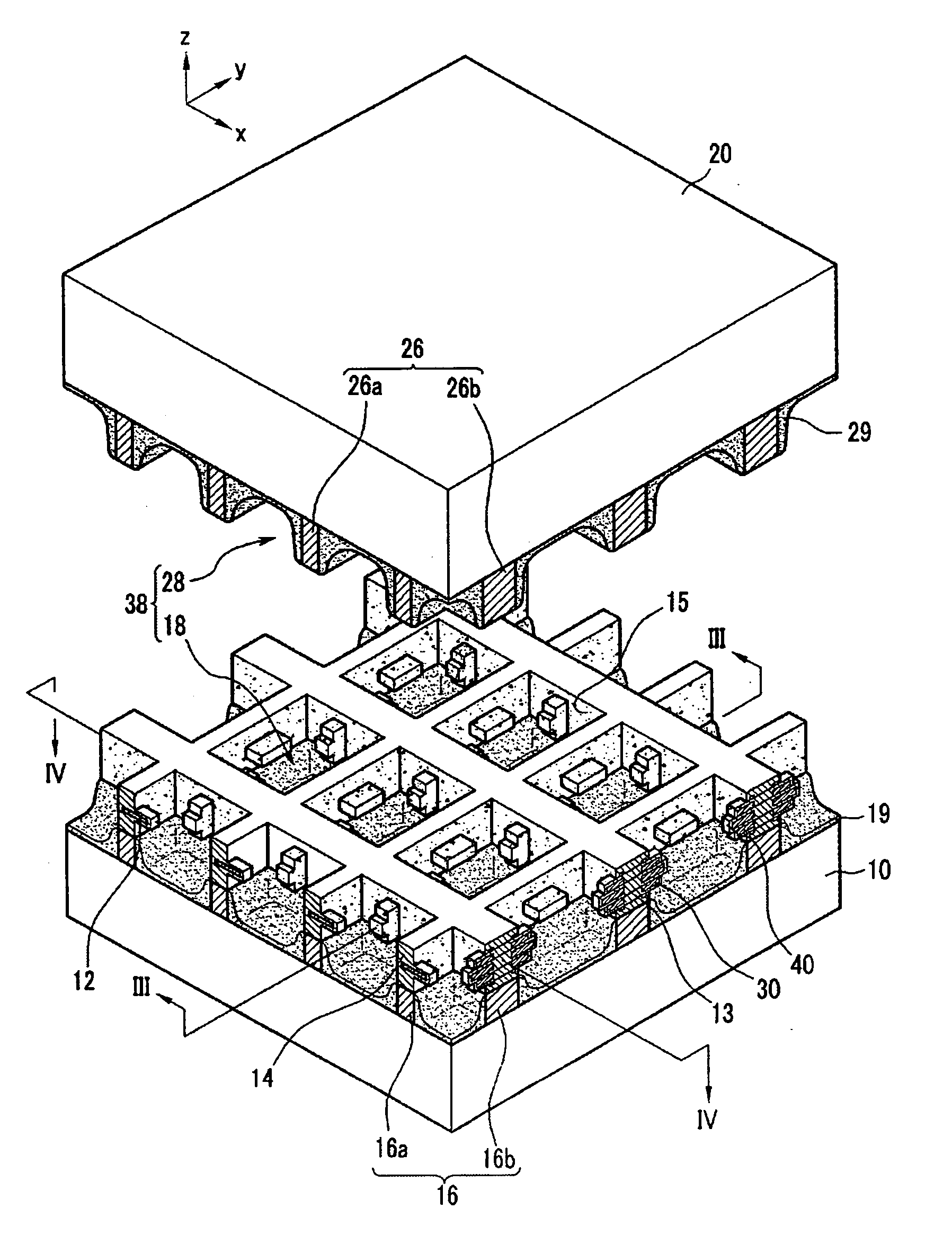
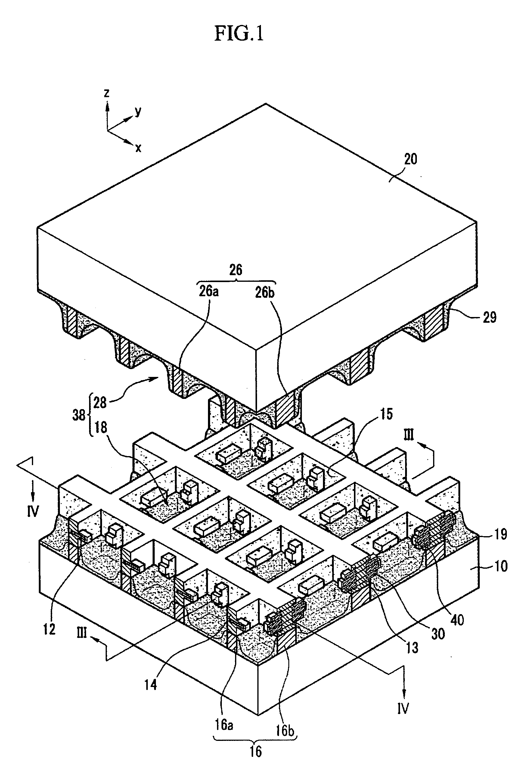
[0041]FIG. 1 is a partial exploded perspective view of a Plasma Display Panel (PDP) according to a first exemplary embodiment of the present invention.

[0042] Referring to FIG. 1, a PDP according to the present exemplary embodiment includes a first substrate 10 (hereinafter called a “rear substrate”) and a second substrate 20 (hereinafter called a “front substrate”) that are disposed facing apart from each other. A space between the rear substrate 10 and the front substrate 20 is partitioned by barrier ribs 16 and 26 into a plurality of discharge cells 38. Phosphor layers 19 and 29 that absorb vacuum ultraviolet (VUV) rays and emit visible light are formed in the discharge cells 38, and a discharge gas (for example, a mixed gas of xenon (Xe), neon (Ne), etc.) is contained within the discharge cells 38.

[0043] The barrier ribs 16 and 26 includes a first barrier rib 16 (hereinafter called a “rear-plate barrier rib”) formed on the rear substrate 10 and protruding toward the front subst...


PUM


Abstract

A Plasma Display Panel (PDP) having enhanced efficiency includes: first and second substrates arranged facing each other and defining a space therebetween partitioned into at least one discharge cell; a phosphor layer arranged in the at least one discharge cell; an address electrode arranged along a first direction in the space between the first and second substrates; and first and second electrodes electrically insulated from the address electrode and arranged along a second direction crossing the first direction at opposite sides of each of the at least one discharge cells in the space between the first and second substrates. At least one of the first and second electrodes includes a plurality of electrode portions that are separate from each other.

Description

CLAIM OF PRIORITY [0001] This application makes reference to, incorporates the same herein, and claims all benefits accruing under 35 U.S.C. §119 from an application for PLASMA DISPLAY PANEL earlier filled in the Korean Intellectual Property Office on 4 Feb. 2005 and there duly assigned Serial No. 10-2005-0010333. BACKGROUND OF THE INVENTION [0002] 1. Field of the Invention [0003] The present invention relates to a Plasma Display Panel (PDP). More particularly, the present invention relates to a PDP structured to realize a high efficiency. [0004] 2. Description of the Related Art [0005] Generally, a Plasma Display Panel (PDP) is a display device which excites phosphors with vacuum ultraviolet (VUV) rays radiated from plasma obtained through a gas discharge, and displays desired images by visible light generated by the excited phosphors. As the PDP allows a wide screen with a high resolution, it has been spotlighted as a future generation flat panel display. [0006] A three-electrode ...

Claims


Application Information

Patent Timeline
IPC IPC(8): H01J61/04H01J11/12H01J11/14H01J11/16H01J11/24H01J11/26H01J11/28H01J11/30H01J11/32H01J11/36H01J11/38H01J11/40H01J11/42H01J11/50
CPCH01J11/16H01J11/32H01J11/36H01J2211/323H01J2211/326
Inventor HUR, MINTAKAHISA, MIZUTA
Owner SAMSUNG SDI CO LTD
Why Eureka
Try Eureka