Electromagnetic rotating machine

a technology of electromagnetic rotating machine and electric resistance, which is applied in the direction of motor/generator/converter stopper, dynamo-electric converter control, and dynamo-electric converter control, etc., can solve the problems of coils having to be excited by the lowest possible electrical power, increasing the weight of engine sections, etc., to reduce the entire weight of electromagnetic rotating machine, reduce the capacity of the charger, and reduce the effect of electric resistance loss

Active Publication Date: 2006-08-10
JAPAN AEROSPACE EXPLORATION AGENCY +1
View PDF17 Cites 24 Cited by
  • Summary
  • Abstract
  • Description
  • Claims
  • Application Information

AI Technical Summary

Benefits of technology

[0031] In the electromagnetic rotating machine of the eleventh invention, since the split excitation coil or the split armature coil is made from the conductive material, electrical resistance loss can be reduced to the minimum when the split excitation coil or the split armature coil is excited, as a result of which the capacity of the charger can be reduced, which can contribute to reduction of the entire weight of the electromagnetic rotating machine.
[0032] According to the electromagnetic rotating machine of the present invention, the excitation coil is disposed on the inner peripheral surface of the fixed body, and the armature coil is disposed on an outer circumference of the rotating body so as to face the excitation coil, thus heavy parts such as an iron core and the like are unnecessary, whereby the weight of the entire machine can be reduced to be lightweight, and also big torque can be produced with small electromagnetic force. Moreover, the excitation coil is configured with a plurality of split excitation coils, and the armature coil is configured with a plurality of split armature coils, wherein, when the vicinity of the central portion of one of the split armature coils overlaps with the vicinity of the central portion of one of the split excitation coils, each of the split excitation coils is disposed on the inner peripheral surface of the fixed body and each of the split armature coils is disposed on the outer circumference of the rotating body, such that the vicinity of the central portion of other split armature coil overlaps with the vicinity of the central portion of other split excitation coil respectively, and other split excitation coils respectively overlap with the split armature coil at both sides thereof. The direction of excitation is preferably controlled such that the split excitation coils act on the split armature coils respectively differently on the basis of a relative position with respect to the split armature coils. Specifically, excitation is preferably controlled s...

Problems solved by technology

Moreover, there is a problem that the weight of the engine section increases due to the iron-core structure of the armature.
Therefore, when applying induced current to the armature coil by changing the magnetic field in time, the induced current also is changed in time, thus there arises a problem that the direction of the induced current has ...

Method used


Image

  • Electromagnetic rotating machine
  • Electromagnetic rotating machine
  • Electromagnetic rotating machine

Examples


embodiment 1

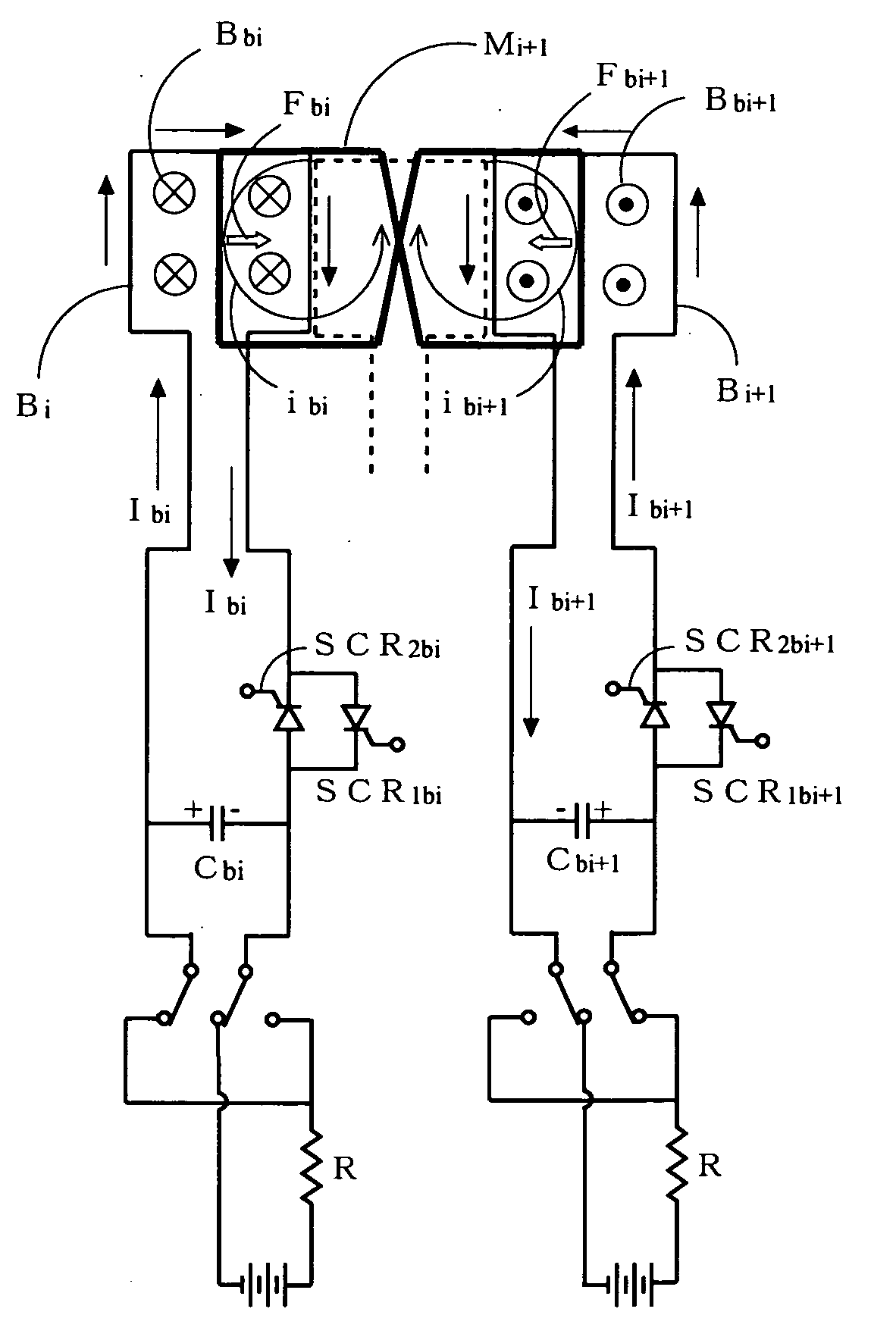
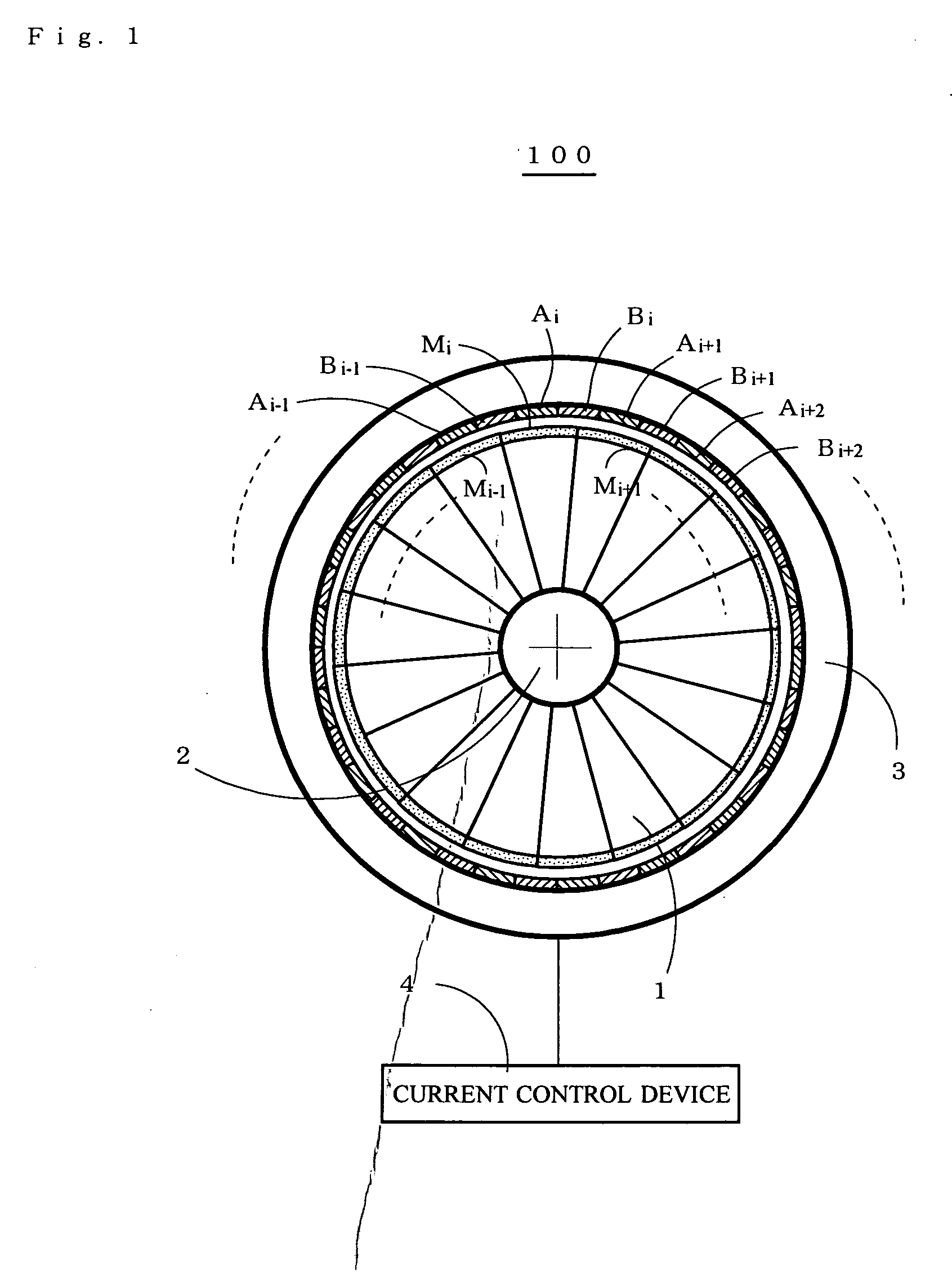
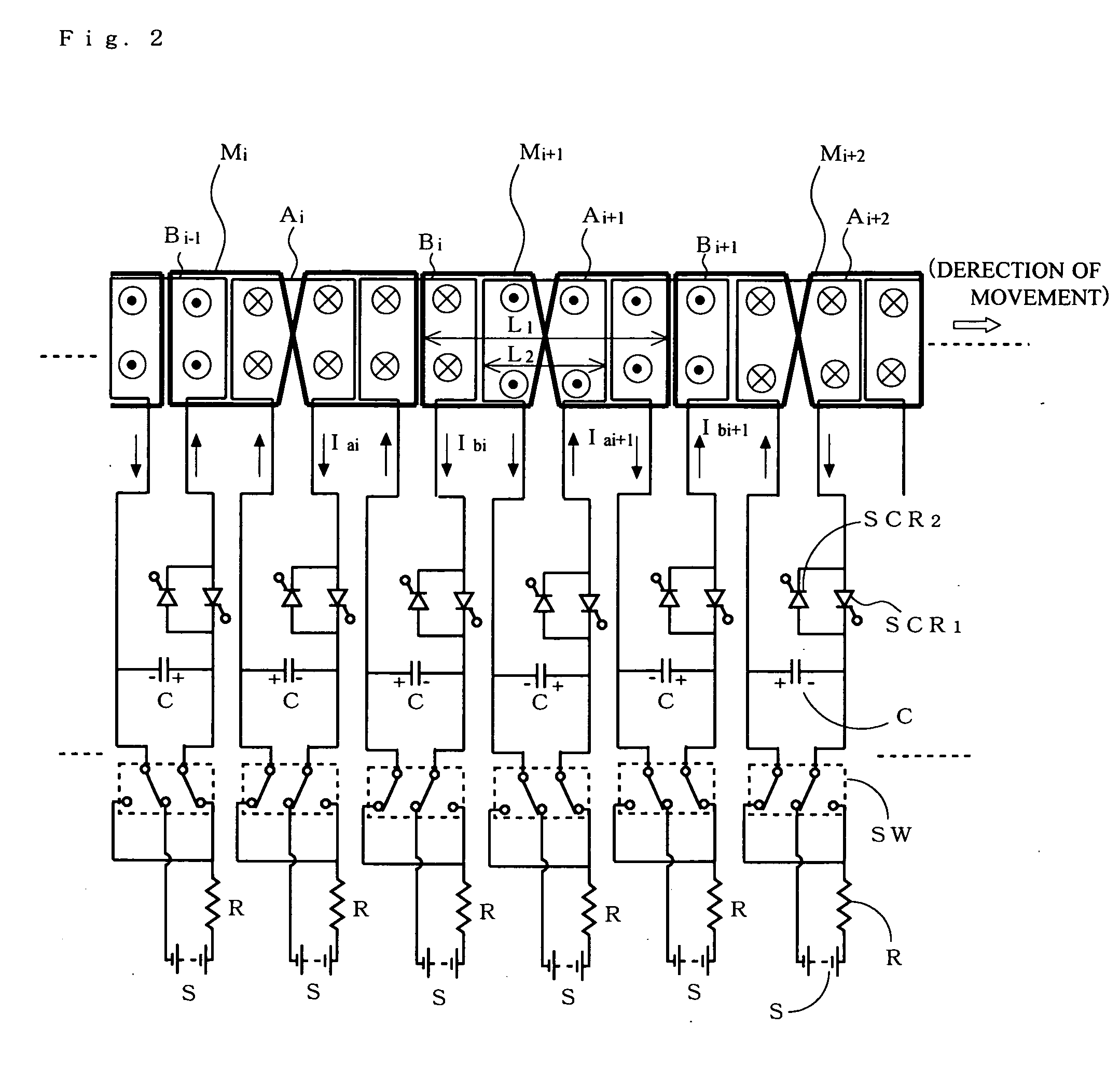
[0042]FIG. 1 is a front view showing a substantial part of an electromagnetic driving fan 100 of an embodiment of the present invention.

[0043] The electromagnetic driving fan 100 comprises a fan blade 1 as a rotating body which increases the flow speed of air which has been taken in and injects the air backward so that thrust in a opposite direction of the injection is produced in response to the injection, a shaft 2 to which the fan blade 1 is attached, a fan casing 3 as a fixed body which stores the fan blade 1 and the shaft 2, a coil Ai row (i=1, 2, . . . , n) as a split excitation coil which is attached to an inner peripheral surface of the fan casing 3 so as to face an outer circumference of the fan blade 1, and generates an effective magnetic field related to effective electromagnetic force for rotating the fan blade 1, a coil Bi row (i=1, 2, . . . , n) as a split excitation coil which applies effective induced current related to the effective electromagnetic force to a split...

embodiment 2

[0078]FIG. 8 is a cross-sectional view showing a substantial part of an electromagnetic rotating machine 200 of other embodiment of the present invention.

[0079] The electromagnetic rotating machine 200 comprises a rotating structure portion 11 as a rotating body which is rotated by effective electromagnetic force, a shaft 2 to which the rotating structure portion 11 is attached, a fixed structure portion 33 as a fixed body which faces the rotating structure portion 11, a coil Ai row as a split excitation coil which is attached to an inner peripheral surface of the fixed structure portion 33 so as to face an outer circumference of the rotating structure portion 11, and generates an effective magnetic field related to effective electromagnetic force for rotating the rotating structure portion 11, a coil Bi row as a split excitation coil which applies effective induced current related to the effective electromagnetic force to a split armature coil which is described hereinbelow, a coi...


PUM


Abstract

In order to obtain an electromagnetic rotating machine of lightweight and high energy efficiency, which produces big torque for rotating a large-diameter fan, a coil A and coil B as excitation coils are disposed on an inner peripheral surface of a fan casing so as to face an outer circumference of the fan, and a coil M as an armature coil crosses at a central portion and is disposed on the outer circumference of the fan. The relationships |Iai|=|Iai+1| and Iai=−Iai+1, or |Ibi|=|Ibi+1| and Ibi=−Ibi+1 are obtained respectively for the coil A or coil B by a current control device (not shown). Moreover, the coil A and coil B are subjected to excitation control such that the direction of effective electromagnetic force, which is generated by an interaction between an effective magnetic field formed by the coil A and effective induced current applied to the coil M by the coil B, corresponds to the direction of rotation of the fan.

Description

BACKGROUND OF THE INVENTION [0001] 1. Field of the Invention [0002] The present invention relates to an electromagnetic rotating machine, and particularly to an electromagnetic rotating machine which is preferred for a turbofan mounted in an airplane. [0003] 2. Description of the Related Art [0004] In a conventional aircraft jet propeller, i.e. turbojet engine, the pressure of the air taken in from an inlet is increased by a compressor, thus obtained compressed air is intermixed with fuel, which is then combusted by a combustor and injected backwards as high-temperature and pressure gas, and propulsion is obtained by means of the reaction force produced by the injection. On the other hand, there is a turbofan engine and the like in which some of the breathed air is caused to bypass and pass through a fan only without being sent to the core engine that consists of a compressor, combustor, and turbine, the flow speed of the air is increased by means of the fan, and then the air is inj...

Claims


Application Information

Patent Timeline
IPC IPC(8): H02P1/24H02K3/28H02K17/16H02P23/00H02P23/07H02P25/10
CPCF02K3/04F02K3/06H02K17/16H02K17/165H02K41/025Y02T50/671F05D2220/323F05D2220/326F05D2220/327F05D2260/903F05D2260/85F05D2260/4041Y02T50/60
Inventor OKAI, KEIICHITAGASHIRA, TAKESHIYANAGI, RYOJINOMURA, HIROSHI
Owner JAPAN AEROSPACE EXPLORATION AGENCY
Why Eureka
Try Eureka