Analog front-end circuit and electronic apparatus

a front-end circuit and analog technology, applied in the direction of electrical devices, pictoral communication, etc., to achieve the effect of reducing the degradation of image data transferred and sufficiently reducing the radiation noise at the cabl

Inactive Publication Date: 2006-08-10
SEIKO EPSON CORP
View PDF2 Cites 24 Cited by
  • Summary
  • Abstract
  • Description
  • Claims
  • Application Information

AI Technical Summary

Benefits of technology

[0007] An advantage of the present invention is to provide an analog front-end circuit that reduces degradation of image data transferred from an image sensor and has a measure against EMI, and also to provide an electronic apparatus including the circuit
[0008] An analog front-end circuit according to one aspect of the invention controls an imaging device and processes an analog image signal output from the imaging device. The analog front-end circuit includes: an analog processor that receives an analog image signal from the imaging device, provides the image signal with predetermined processing, and outputs a resultant signal; an A/D converter that performs A/D conversion with the image signal output from the analog processor; a holding circuit that holds digital image data output from the A/D converter; a timing generator that, based on a first reference clock, generates a plurality of clocks and outputs the clocks to at least one of the analog processor and the A/D converter; and a spread spectrum modulation circuit that performs spread spectrum modulation with the first reference clock and outputs a resultant clock that has been subject to the spread spectrum modulation as a modulated clock to the holding circuit; wherein the holding circuit holds the digital image data from the A/D converter based on the modulated clock output from the spread spectrum modulation circuit.
[0009] With this structure, the holding circuit holds the image data based on the modulated clock, thereby outputting the image data as a signal that has been subject to the spread spectr

Problems solved by technology

Therefore, the image sensor having the head-side substrate coupled with the main substrate via a long cable involves problems including radiation nois

Method used


Image

  • Analog front-end circuit and electronic apparatus
  • Analog front-end circuit and electronic apparatus
  • Analog front-end circuit and electronic apparatus

Examples


Embodiment Construction

[0046] An embodiment of the invention will be described with reference to the accompanying drawings. The embodiment described below is not intended to unreasonably limit the invention set forth in the claims. Also, it should be understood that not all of the elements described below are required to put the invention into practice.

1. Image Sensor

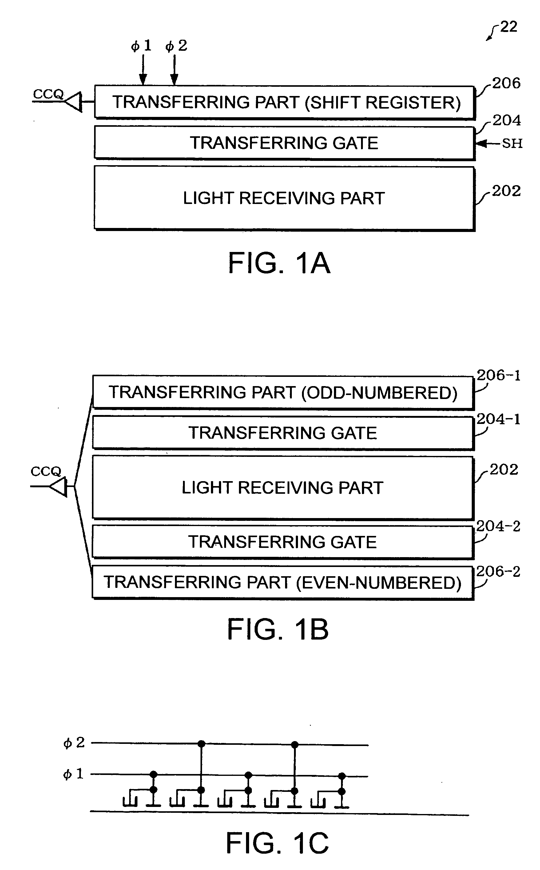
[0047]FIG. 1A shows a configuration example of an image sensor 22 (imaging device in a broad sense). This image sensor 22 (e.g. CCD line sensor) includes a light receiving part 202, a transferring gate 204 and a transferring part (shift register) 206, for example. The light receiving part 202 includes a plurality of light receiving elements (photodiodes, pixels) for photoelectric conversion. Note that like numerals indicate like elements throughout the drawings.

[0048] Each light receiving element (pixel) included in the light receiving part 202 generates and accumulates charges depending on the amount of light it receives. After a given p...


PUM


Abstract

An analog front-end circuit that controls an imaging device and processes an analog image signal output from the imaging device comprises: an analog processor that receives an analog image signal from the imaging device, provides the image signal with predetermined processing, and outputs a resultant signal; an A/D converter that performs A/D conversion with the image signal output from the analog processor; a holding circuit that holds digital image data output from the A/D converter; a timing generator that, based on a first reference clock, generates a plurality of clocks and outputs the clocks to at least one of the analog processor and the A/D converter; and a spread spectrum modulation circuit that performs spread spectrum modulation with the first reference clock and outputs a resultant clock that has been subject to the spread spectrum modulation as a modulated clock to the holding circuit; wherein the holding circuit holds the digital image data from the A/D converter based on the modulated clock output from the spread spectrum modulation circuit.

Description

BACKGROUND OF THE INVENTION [0001] 1. Technical Field [0002] The present invention relates to an analog front-end circuit and an electronic apparatus. [0003] 2. Related Art [0004] An image sensor used in an image scanner or the like acquires image signals of image data at its light receiving part and incorporates the signals in its transferring part. The transferring part then receives a driving clock from an image sensor controller that controls the image sensor. Using this clock, the transferring part sequentially shifts and transfers the image data to the outside. [0005] A kind of image scanner has been known to read images using a head-side substrate (carriage) on which a line-shaped image sensor is mounted. When reading images, the head-side substrate is driven by a servomotor or the like, so that its reading position will change step by step. Since the head-side substrate is thus movable, it is coupled with a main substrate having, for example, a circuit for generating a contr...

Claims


Application Information

Patent Timeline
IPC IPC(8): H04N1/04
CPCH04N1/0473H04N1/1013H04N1/192H04N2201/0477H04N2201/04774
Inventor MIZUTA, MASAHIKOKIMURA, KENJI
Owner SEIKO EPSON CORP
Why Eureka
Try Eureka