Heat Sink Fan and Method for Manufacturing Heat Sink That Is Used for the Heat Sink Fan

a technology of heat sink fan and heat sink fan, which is applied in the direction of lighting, heating apparatus, and mechanical devices. it can solve the problems of insufficient flow, inability to dissipate enough air, and inability to so as to increase the quantity of air flow and improve the cooling efficiency of the heat sink

Active Publication Date: 2006-08-10
NIDEC CORP
View PDF3 Cites 7 Cited by
  • Summary
  • Abstract
  • Description
  • Claims
  • Application Information

AI Technical Summary

Benefits of technology

[0011] An object of the present invention is to provide a heat sink fan that can increase quantity of air flow from an axial flow fan so as to improve cooling efficiency of a heat sink.
[0012] Another object of the present invention is to reduce a number of components that constitute a structure for attaching a fan motor unit having the axial flow fan to the heat sink so as to realize a simplest structure.
[0013] Still another object of the present invention is to reduce a cost of manufacturing the heat sink fan.
[0014] Still another object of the present invention is to attach the fan motor unit to the heat sink more steadily and more securely.
[0017] According to this structure, the fan motor unit can be attached to the heat sink steadily and securely.
[0019] According to this structure, protrusion or recess of the heat sink can be formed easily and precisely.

Problems solved by technology

However, if a rotation speed of the axial flow fan is increased so as to enhance the cooling efficiency for satisfying the above-mentioned requirement, the following problem may happen.
Namely, the above-mentioned structure in which four arm portions extend from the housing to the substrate provided at the lower end of the heat sink has a disadvantage that when the air flow supplied by the axial flow fan flows along the heat radiating fins and is dissipated outside the heat sink, the arm portions disposed at the outer side of the heat radiating fins may interrupt the air flow.
As a result, the air flow cannot be dissipated sufficiently into the outside of the heat sink, so that the cooling efficiency of the heat sink may be deteriorated.
As a result, the arm portions become easy to generate a distortion such as warping at the tip of the arm portion when housing is formed by resin molding.
Consequently, it becomes difficult to finish precisely an engaging portion such as the pawl portion at the tip of the arm portion.
In this case, it becomes difficult to attach the fan motor unit to the heat sink properly.

Method used


Image

  • Heat Sink Fan and Method for Manufacturing Heat Sink That Is Used for the Heat Sink Fan
  • Heat Sink Fan and Method for Manufacturing Heat Sink That Is Used for the Heat Sink Fan
  • Heat Sink Fan and Method for Manufacturing Heat Sink That Is Used for the Heat Sink Fan

Examples


first embodiment

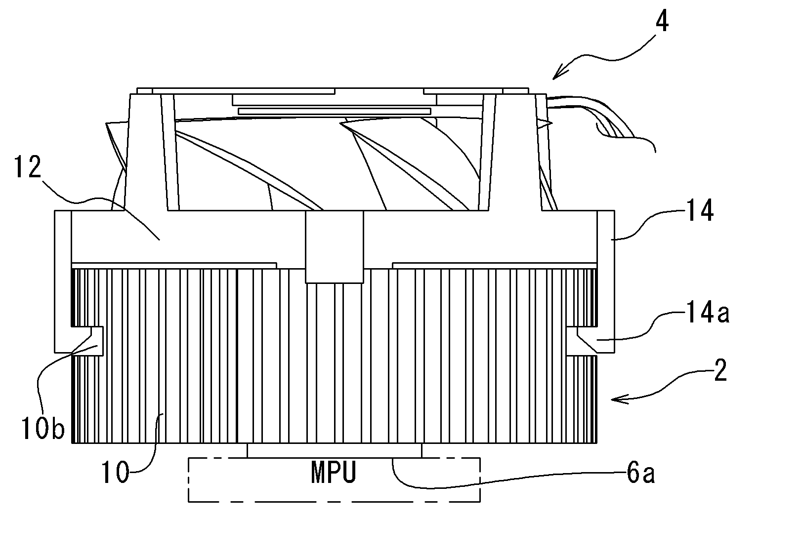
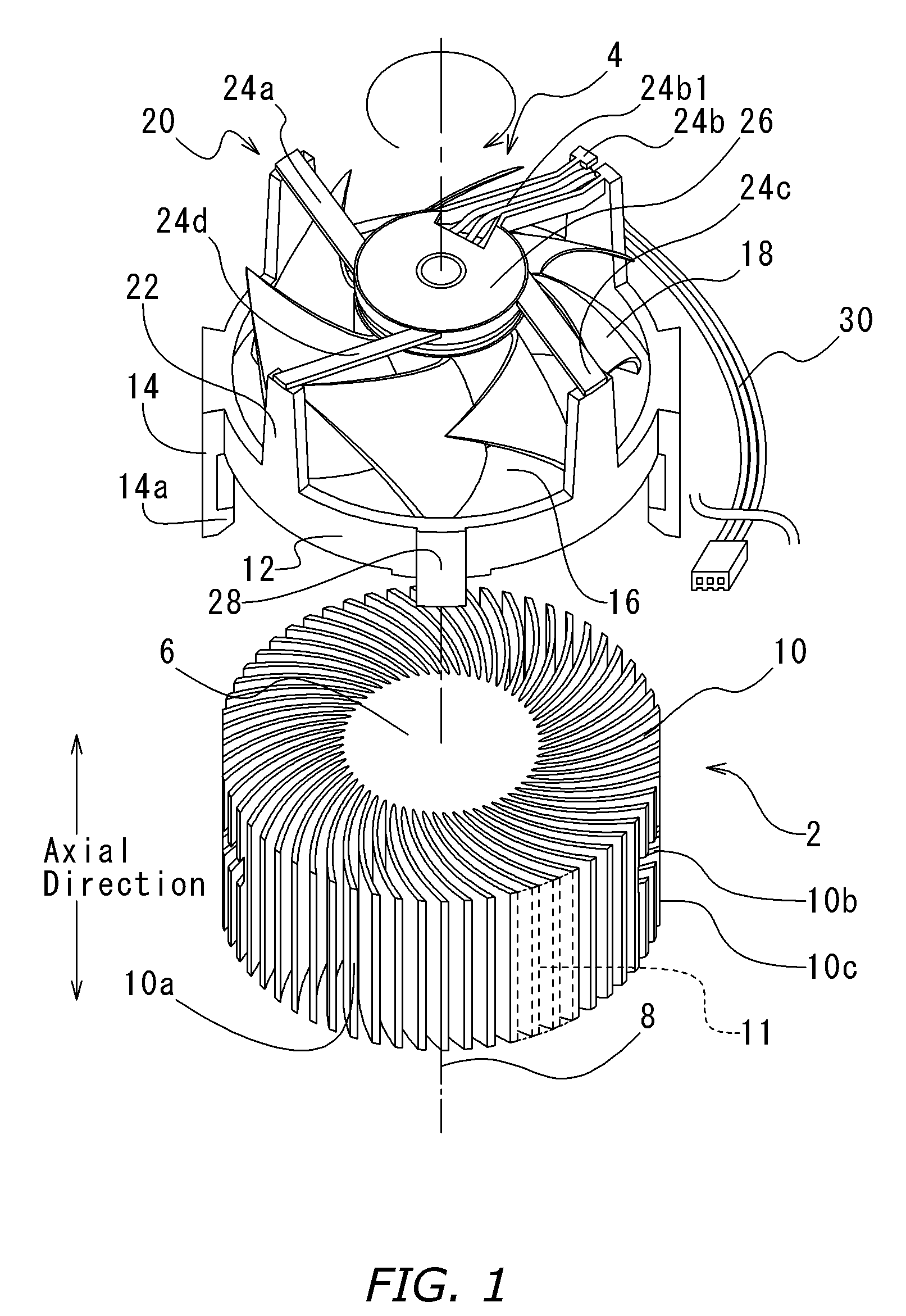
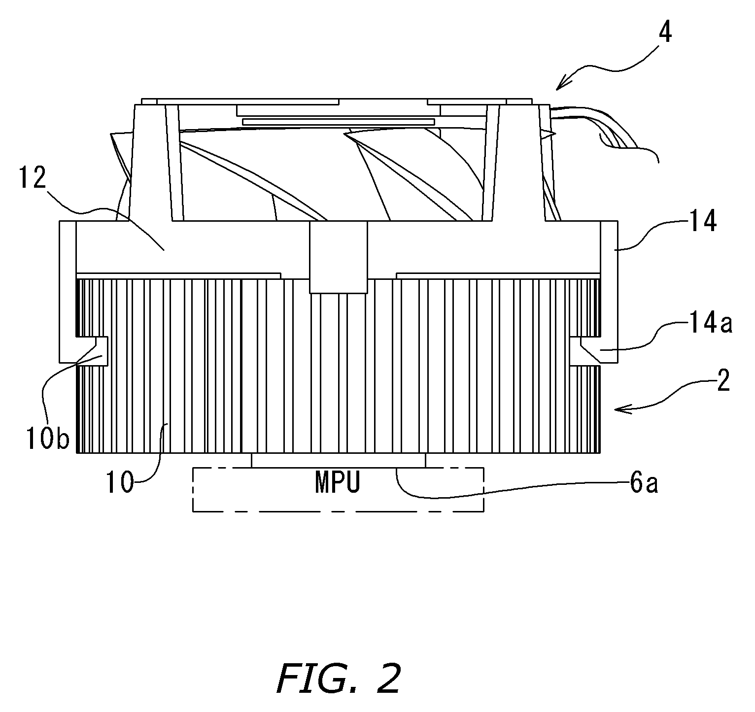
[0027] As shown in FIG. 1, a heat sink fan according to the present invention includes a heat sink 2 and a fan motor unit 4 that is detachably attached to the heat sink 2.

[0028] The heat sink 2 is a substantially circular member, which is made of aluminum, aluminum alloy, copper, copper alloy or other metal having relatively high thermal conductivity by an extrusion or other processes. The heat sink 2 includes a column-like base portion 6 having a lower end surface (6a in FIG. 2) that is placed on an MPU or other electronic component and a central axis 8 that is perpendicular to the lower end surface 6a. The heat sink 2 has a plurality of heat radiating fins 10 that are connected integrally to the outer peripheral surface of the base portion 6 and extending radially away from the central axis. The heat radiating fins 10 are arranged and distributed equally in the circumferential direction. Each of the heat radiating fins 10 radially extends with a curved shape from the base portion ...

third embodiment

[0056] Next, the present invention will be explained in detail with reference to FIG. 6. The heat sink 52 of this embodiment has a substantially rectangular shape, which is made of aluminum, aluminum alloy, copper, copper alloy or other material having high thermal conductivity by extrusion or other process. The heat sink 52 has a lower end surface that is placed on an MPU or other electrical component and a substantially rectangular base portion 56 with a central axis 58 that is perpendicular to the lower end surface. In addition, the heat sink 52 has leg portions 56d that are formed integrally to the outer periphery of the base portion 56 and extend from edge portions on the outer periphery of the base portion 56 outward in the direction away from the central axis 58. The heat sink 52 also has a plurality of heat radiating fins 60 that extend from the base portion 56 and the leg portions 56d in the direction away from the central axis 58. Each of the heat radiating fins 60 has an ...


PUM

PropertyMeasurementUnit
speedaaaaaaaaaa
lengthaaaaaaaaaa
thermal conductivityaaaaaaaaaa

Abstract

A heat sink fan includes a heat sink (2) that is placed on a heat generating electrical component and a fan motor unit (4) having an axial flow fan (18) for supplying cooling air to the heat sink (2). A engaging portions (14a) of an arm portions (14) of the fan motor unit (4) is engaged with a recesses (10b) of the heat sink (2). Thus, movement of the fan motor unit (4) in the axial direction of the heat sink (2) is restricted so that the fan motor unit (4) is attached to the heat sink (2) securely.

Description

BACKGROUND OF THE INVENTION [0001] 1. Technical Field [0002] The present invention relates to a heat sink fan for cooling a micro processing unit (MPU) or other electrical component and a method for manufacturing a heat sink that is used for the heat sink fan. [0003] 2. Description of the Related Art [0004] A heat sink fan that is attached to an MPU or other heat generating electrical component usually includes a heat sink having a plurality of heat radiating fins that are placed on a MPU and extend radially from the central portion. The heat sink fan also includes a fan motor unit that has an axial flow fan with an impeller, which is surrounded by the heat radiating fins and is disposed at the central portion of the heat sink and at the inner side of the heat radiating fins. The heat radiating fins of the heat sink are cooled by air flow supplied by the axial flow fan. [0005] One of structures for attaching the fan motor unit to the heat sink is disclosed in U.S. Pat. No. 6,419,007...

Claims


Application Information

Patent Timeline
Patent Type & Authority Applications(United States)
IPC IPC(8): H05K7/20G12B15/06H01L23/36H01L23/467
CPCH01L23/467H01L2924/0002Y10T29/49359Y10T29/4938Y10T29/53178Y10T29/4935Y10T29/4913Y10T29/49364Y10T29/53174Y10T29/49377H01L2924/00
Inventor OTSUKI, TAKAYAISHIKAWA, MASAHIRO
Owner NIDEC CORP
Why Eureka
Try Eureka