
Data transfer apparatus and multicast system

Inactive Publication Date: 2006-08-10
HITACHI LTD
View PDF7 Cites 50 Cited by
  • Summary
  • Abstract
  • Description
  • Claims
  • Application Information

AI Technical Summary

Benefits of technology

[0016] For an actual operation, a network is often arranged to have a topology including redundant routes to enhance reliability. The reason that the redundant routing increases the reliability is because a certain route, in which a failure has occurred, can be switched into another route.
[0026] Accordingly, since one DR is determined in each link, duplicated transmission of multicast data is avoided. In addition, upon the occurrence of routing failure, the DR as well as the QRY is switched into another passive PIM multicast router made redundant, so the multicast distribution route is switched into a redundant route, thereby solving Problem 2.
[0029] Further, a similar effect is also produced by applying the above-mentioned measure to a case where a multicast router neighboring the multicast transmitting terminal transmits a PIM control message obtained by encapsulating multicast data to a core router called a rendezvous point (RP).
[0031] Further, even among redundant multicast distribution routes which are arranged using a passive PIM router providing a limited operation based on PIM in terms of security to be made redundant, it is possible to avoid the multicast receiving terminal from receiving a multicast packet duplicatedly by determining only the one serving as a QR to be a DR.

Problems solved by technology

If a terminal or a server operated by a malicious user is connected to the multicast network from a neighboring location, it is possible for the user to easily cause confusion in the control of the multicast network based on PIM.

Method used


Image

  • Data transfer apparatus and multicast system
  • Data transfer apparatus and multicast system
  • Data transfer apparatus and multicast system

Examples


embodiment 1

[0045] Hereinafter, an IGMP / MLD proxy router according to an embodiment of the present invention is described.

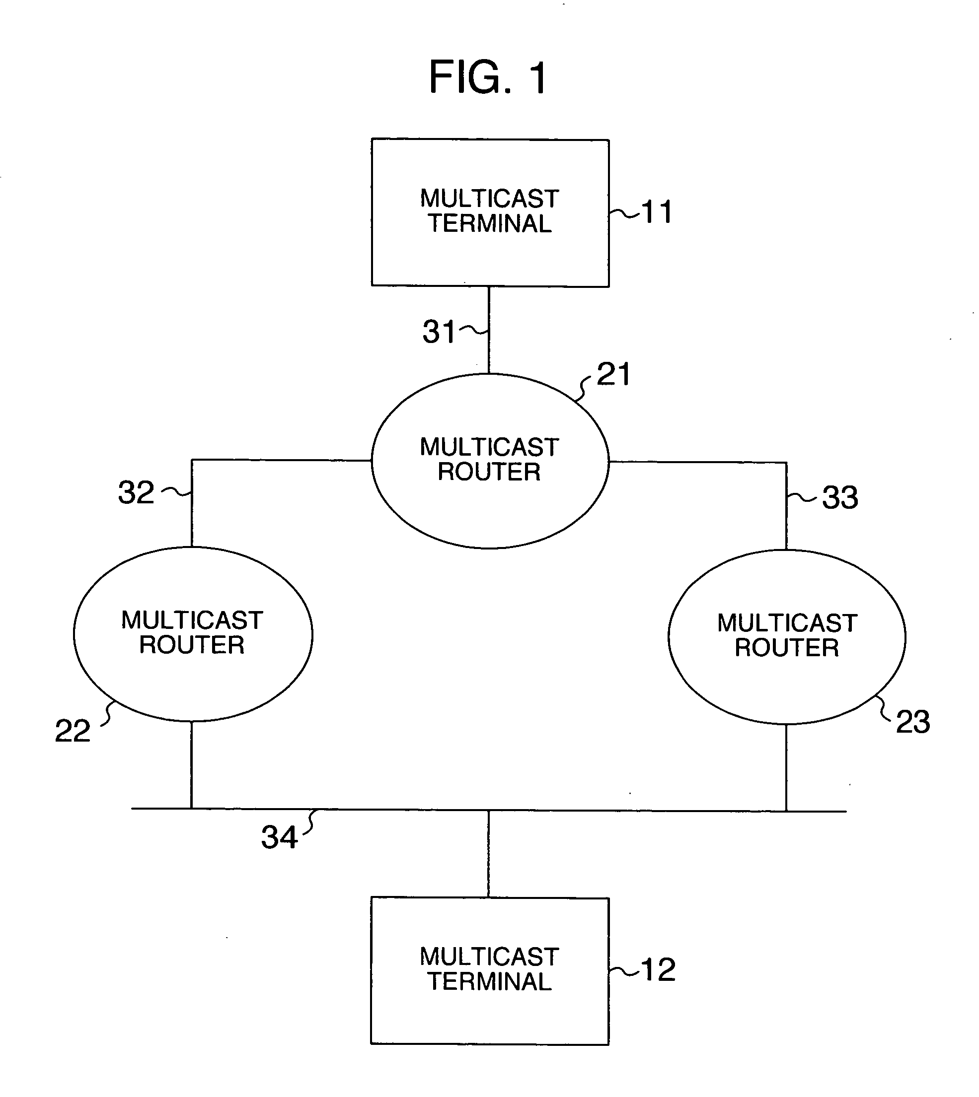
[0046] Referring to the schematic diagram of FIG. 1, the network arrangement is described. In FIG. 1, a multicast terminal 11 is a multicast transmitting terminal as a transmission source of multicast data, a multicast terminal 12 is a multicast receiving terminal for receiving the multicast data, a multicast router 21 transfers the multicast data, and multicast routers 22 and 23 are IGMP / MLD proxy routers for transferring a request to receive multicast data in IGMP / MLD, from the multicast receiving terminal 12 to the multicast router 21.

[0047] Referring to a sequence diagram of FIG. 3 and a processing flowchart of FIG. 4, an operation of the present invention is described.

[0048] The IGMP / MLD proxy routers 22 and 23 mutually send / receive a control message for determining a QRY of the IGMP / MLD on a link 34 of FIG. 1, through the link 34, and a priority of a router as the Q...

embodiment 2

[0061] A passive PIM multicast router according to an embodiment of the present invention is described.

[0062] Referring to a schematic diagram of FIG. 1, the network arrangement is described. In FIG. 1, the multicast terminal 11 is a multicast transmitting terminal as a transmission source of multicast data, the multicast terminal 12 is a multicast receiving terminal for receiving the multicast data, the multicast router 21 distributes the multicast data, and the multicast routers 22 and 23 are passive PIM multicast routers receiving a request to receive multicast data in IGMP / MLD, from the multicast receiving terminal 12, and sending a request to receive multicast data in PIM, to the multicast router 21.

[0063] Referring to a sequence diagram of FIG. 5 and a processing flowchart of FIG. 6, an operation of the present invention is described.

[0064] The passive PIM multicast routers 22 and 23 mutually send / receive a control message for determining a QRY of the IGMP / MLD on the link 3...

embodiment 3

[0079] A multicast router according to another embodiment of the present invention is described.

[0080] Referring to a schematic diagram of FIG. 1, the network arrangement is described. In FIG. 1, the multicast terminal 11 is a multicast transmitting terminal as a transmission source of multicast data, the multicast terminal 12 is a multicast receiving terminal for receiving the multicast data, the multicast router 21 distributes the multicast data, and the multicast routers 22 and 23 are IGMP / MLD proxy routers for receiving a request to receive multicast data in IGMP / MLD, from the multicast receiving terminal 12 and sending a request to receive multicast data in PIM to the multicast router 21.

[0081] Referring to a sequence diagram of FIG. 7 and a processing flowchart of FIG. 8, an operation of the present invention is described.

[0082] The multicast routers 22 and 23 mutually send / receive a control message for determining a DR of the PIM on the link 34 of FIG. 1, through the link ...


PUM


Abstract

By transmitting / receiving a multicast receiving terminal management message, a router to be a starting point upon creation of a multicast route is determined based on a multicast routing protocol, and switched according to a state of a multicast transmitting terminal side network. Accordingly, when a trouble occurs in the transmitting terminal side network, it becomes possible to perform switching into a redundant network.

Description

INCORPORATION BY REFERENCE [0001] The present application claims priority from Japanese application JP2005-028373 filed on Feb. 4, 2005, the content of which is hereby incorporated by reference into this application. BACKGROUND OF THE INVENTION [0002] The present invention relates to a multicast network, and more particularly to a technique of controlling a multicast relay route. [0003] Multicast is a technique of allowing data transmitted one time to be received by plural terminals (hereinafter, a terminal for transmitting multicast data is referred to as a “multicast transmitting terminal”, a terminal for receiving multicast data is referred to as a “multicast receiving terminal”, and a router for transferring the multicast data is referred to as a “multicast router”). Used for routing the multicast data are one protocol between a multicast receiving terminal and a multicast router and another different protocol between a multicast router and a multicast router. [0004] Protocols c...

Claims


Application Information

Patent Timeline
IPC IPC(8): G01R31/08H04J3/26H04L45/16H04L45/24H04L45/247
CPCH04L12/185H04L12/1863H04L45/00H04L45/16H04L45/22H04L45/28
Inventor SHIBATA, TAKESHI
Owner HITACHI LTD
Learn More