Communication system using multiple link terminals for aircraft

a communication system and terminal technology, applied in the field of mobile communication systems, can solve the problems of single dynamic link degrade, low link quality, and prior known system typically not providing reliable links, and achieve the effect of rapid deploymen

a communication system and terminal technology, applied in the field of mobile communication systems, can solve the problems of single dynamic link degrade, low link quality, and prior known system typically not providing reliable links, and achieve the effect of rapid deploymen

US20060178143A1Inactive Publication Date: 2006-08-10THE DIRECTV GROUP

Image

  • Communication system using multiple link terminals for aircraft
  • Communication system using multiple link terminals for aircraft
  • Communication system using multiple link terminals for aircraft

Examples


Embodiment Construction

[0043] In the following description, the same reference numerals are used to identify the same components in the various views. Those skilled in the art will recognize that various other embodiments, structural changes and changes in measures may be made without departing from the scope of the invention. The following description is described with respect to mobile terminals. Although the advantages are suitable in mobile applications, the present invention could be used for fixed terminals.

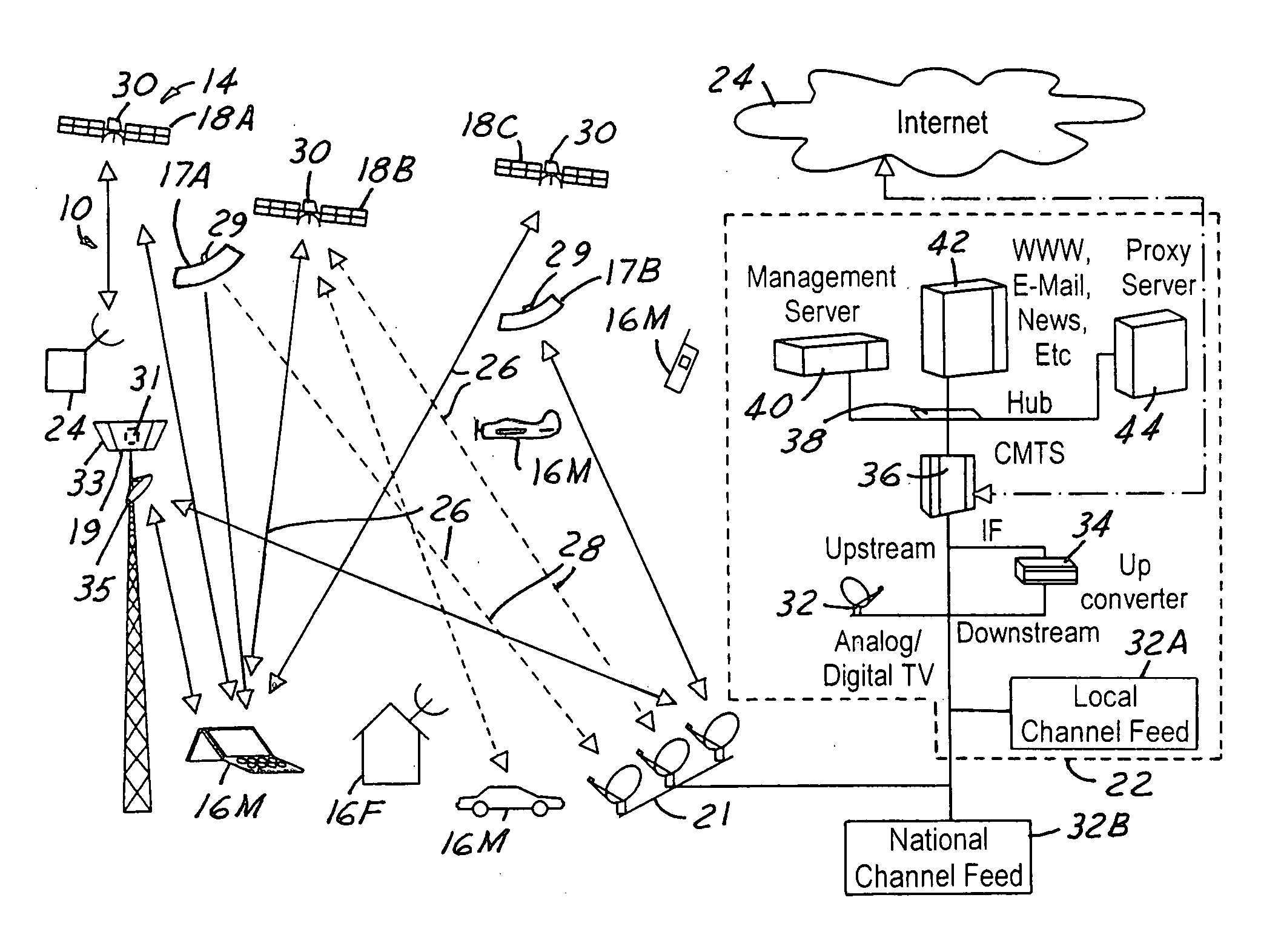
[0044] Referring now to FIG. 1, a communications system 10 is used to couple a plurality of user terminals 16M and 16F with a multiple link communication infrastructure 14. Infrastructure 14 may include a plurality of high altitude communications devices such as stratospheric platforms 17A, 17B and / or satellite constellations having satellites 18A, 18B and 18C, and terrestrial based cell tower 19. Satellites 18A, 18B, 18C may also represent satellites in a respective first constellation, second ...


PUM


Abstract

A communication system has a communication infrastructure and a gateway station communicating a communication signal to the communication infrastructure. An airplane having an antenna coupled to a processing circuit for establishing a plurality of multiple communication links corresponding to the communication infrastructure is used. The gateway station generates multiple datagrams from the television signal and transmits the multiple datagrams through the multiple dynamic links. The antenna receives the datagrams from the infrastructure and the processing circuit and reassembles the datagrams into the communication signal.

Description

RELATED APPLICATIONS [0001] The present application is a Continuation of U.S. patent application Ser. No. 09 / 967,757 filed Sep. 28, 2001, which is a Continuation-In-Part of U.S. patent application Ser. No. 09 / 735,860 filed on Dec. 12, 2000, which are incorporated by reference herein.TECHNICAL FIELD [0002] The present invention relates generally to mobile communication systems, and more particularly to a communication system that uses multiple links for effectively communicating with passengers on an aircraft. BACKGROUND ART [0003] In this communication age, content providers are increasingly investigating ways in which to provide more content to users as well as interfacing with users. [0004] Communication satellites have become commonplace for use in many types of communication services, e.g., data transfer, voice communications, television spot beam coverage, and other data transfer applications. In particular, data transfer may include coupling to the Internet to take advantage o...

Claims


Application Information

Patent Timeline
10 Aug 2006
Publication
US20060178143A1
IPC
H04Q7/20; H01Q1/00; H01Q1/22; H01Q3/26; H04B7/04; H04B7/185; H04W84/06
CPC
H01Q1/007; H01Q3/26; H04B7/0408; H04B7/18506; H04B7/18508; H04W84/06
Inventors
CHANG, DONALD C. D.; LIM, WAH L.