Apparatus for attaching sutures

a technology for attaching sutures and sutures, which is applied in the field of suture anchors, can solve the problems of eyelet failure, known suture anchor damage, and the structure of the anchor is vulnerable to breakage, and achieves the effect of increasing the procedural options for the surgeon and being convenient to attach sutures

Inactive Publication Date: 2006-08-10
INION
View PDF20 Cites 102 Cited by
  • Summary
  • Abstract
  • Description
  • Claims
  • Application Information

AI Technical Summary

Benefits of technology

[0005] An advantage is that the anchor attaches firmly to the tissue, due to the rotational movement and the co-operation of the intruding edge and the abutment surface. Another advantage is that because the intruding edge and the abutment surface are connected together by the connecting part of the perimeter having a substantially continuous cross-section, the operator may rotate the anchor smoothly and in a controlled way from its insertion position to its attaching position.
[0006] According to one embodiment of the present invention, the anchor comprises at least one slot for at least one suture, said slot being arranged transversal in respect of the longitudinal cross-section, and being connected to the perimeter by a passageway. An advantage is that one or more sutures may be threaded at its intermediate portion to the slot, which makes it easier to attach sutures to the anchor, and can enable said suture to be first permanently connected to a ligature, and / or another anchor, greatly increasing the procedural options for the surgeon, and eliminating the need for suture “shuttle” devices.
[0007] According to one embodiment of the present invention, the perimeter of the anchor body comprises a protruding part at the perimeter that is arranged on the other side of the perimeter in relation to the connecting part. An advantage is that the protruding part establishes a point of support against the wall of the opening, which point of support induces the anchor to begin its rotation towards a position where it will be attached to the tissue.
[0009] An advantage of the insertion tool is that it simplifies the insertion and attaching procedure because both the anchor and the suture can be controlled with it through the whole insertion operation.
[0011] An advantage is that by means of the device it is possible to produce holes, e.g. In bony tissue, which has an internally situated extension part. Said extension part can facilitate the rotation of a suture anchor from its insertion position to an attaching position.

Problems solved by technology

However, known suture anchors suffer from several disadvantages.
The structure of the anchor may be vulnerable to breakage due to mechanical stresses affecting the anchor during its fixation to tissue.
For example, eyelet failures have been reported to originate from stresses that are caused when sutures attached to the anchor are pulled taut.
Sutures can become twisted during the insertion of screw type anchors, hindering the completion of the repair in most conventional anchors, the suture eyelet is a small ring, or a hole that forms a pulley surface to enable suture running.
These conventional anchors can suffer from problems including suture running friction due to the small radius of the pulley aspect of the eyelet, and suture damage due to sharp portions of the anchor near the suture running path.
Furthermore, the pull-out strength, i.e. the force needed to pull the anchor out of the hole where it has been fixed, may be quite low.
The insertion and fixation procedure of the anchor may be complicated and include several steps requiring extreme intentness by the operator executing the operation.
Furthermore, known tools and devices that are used to attach anchors to a bony tissue may be unpractical from the standpoint of the operator.

Method used


Image

  • Apparatus for attaching sutures
  • Apparatus for attaching sutures
  • Apparatus for attaching sutures

Examples


Embodiment Construction

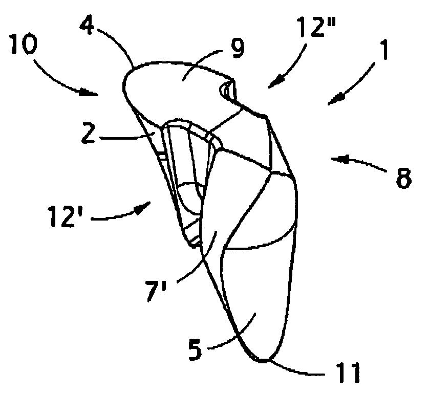
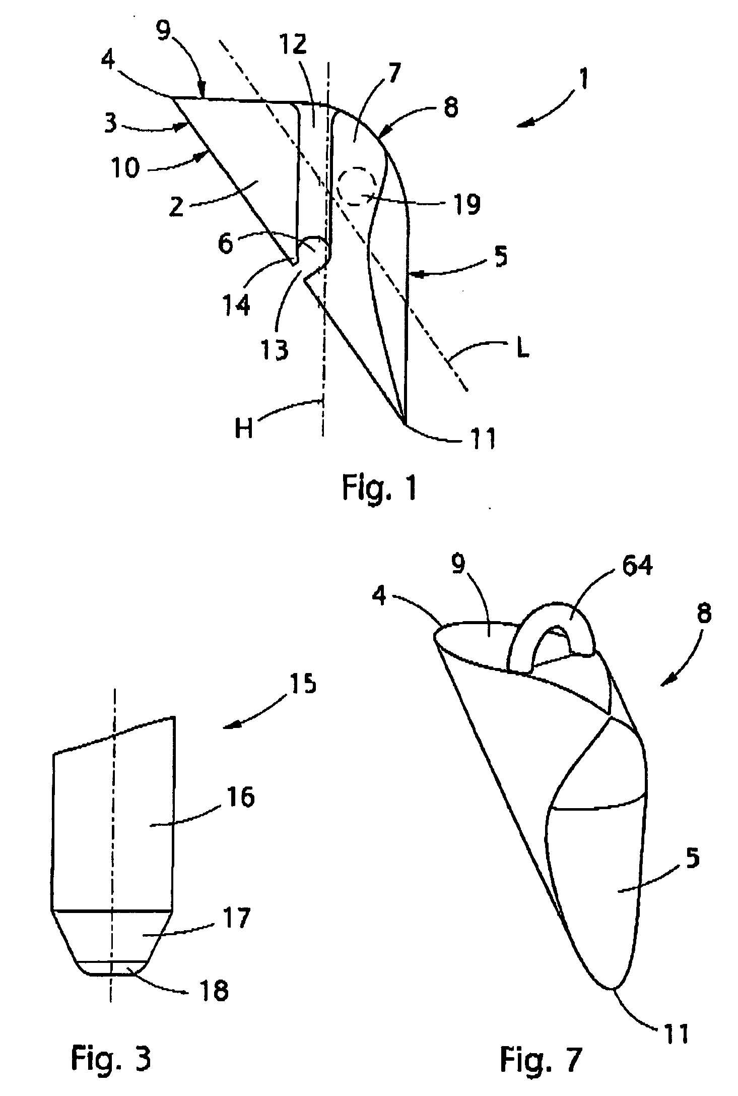
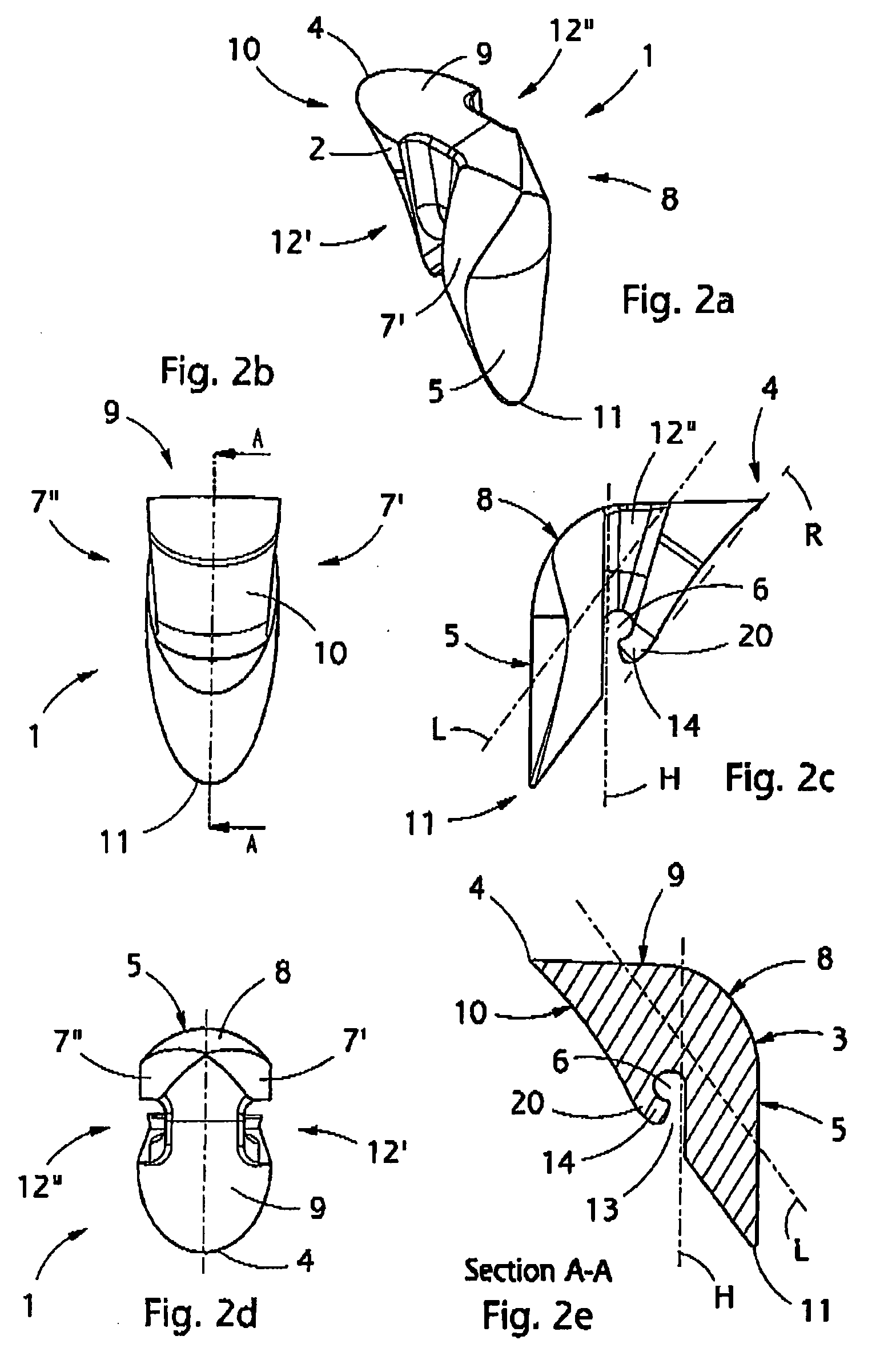
[0030]FIG. 1 is a schematic side view of a suture anchor according to the present invention.

[0031] The suture anchor comprises an anchor body 2, which is preferably made of a biodegradable polymer material that absorbs into the organ system and is prepared by polymerising or copolymerising for instance lactic acid, L-lactide, D-lactide, D, L-lactide, mesolactide, glycolic acid, glycolide or a cyclic ester copolymerised with lactide, or of any other corresponding material known per se to a person skilled in the art, which will not be discussed in this context in greater detail. Other suitable biodegradable polymers, copolymers and polymer mixtures are listed in the following publications, for instance: [0032]“Encyclopedic handbook of Biomaterials and Bioengineering, Part A,” Donald, L. Wise, Debra J. Trantolo, David E. Altobelli, Michael J. Yaszemski, Joseph D. Gresser, Edith R. Schwartz, 1992, by Marcel Dekker, Inc., pages 977 to 1007, [0033]“Biodegradable fracture-fixation devices...


PUM


Abstract

A suture anchor, an insertion tool for inserting a suture anchor, and a device for internal working of hole in bony tissue. The anchor comprises an anchor body having a longitudinal cross-section defined by a perimeter. The perimeter comprises at least one tissue-intruding edge formed between the first side and the second side of the perimeter. The intruding edge is arranged to penetrate the tissue during a rotating motion of the anchor in said opening. The anchor further comprises an abutment surface, arranged substantially on the opposite side of the anchor body in relation to said intruding edge. The first side of the intruding edge is arranged to connect with the abutment surface by a connecting part of the perimeter having the shape of a substantially curved piece in said longitudinal cross-section.

Description

BACKGROUND OF THE INVENTION [0001] The invention relates to an apparatus for attaching sutures to a human tissue. More particularly, the invention relates to a suture anchor made of preferably biodegradable material absorbing into the body, an insertion tool having an insertion end for inserting and attaching the anchor to a tissue, and a device for internal working of a hole in live human tissues. [0002] Suture anchors for attaching a suture to a bony tissue so that another body tissue, e.g. ligament or muscle, may be sutured to the bony tissue are known. Such anchors, as well as devices that are used to attach anchors to a bony tissue, are disclosed, for example, in U.S. Pat. Nos. 5,522,844, 5,540,718, 5,683,418, 5,807,403, 6,007,566 and 6,183,479, each of which are hereby incorporated by reference in their entireties for all purposes. [0003] However, known suture anchors suffer from several disadvantages. The structure of the anchor may be vulnerable to breakage due to mechanical...

Claims


Application Information

Patent Timeline
Patent Type & Authority Applications(United States)
IPC IPC(8): A61B17/04
CPCA61B17/0401A61B17/1617A61B2017/00004A61B2017/00893A61B2017/0409A61B2017/0414A61B2017/0417A61B17/00A61B17/04
Inventor PIERCE, JAVIN CEDVICKARHI, OLLIVUORISALO, VESAPIRHONEN, EIJAHAPPONEN, HARRI
Owner INION
Why Eureka
Try Eureka