Control apparatus and method for internal combustion engine

a control apparatus and internal combustion engine technology, applied in the direction of electrical control, process and machine control, instruments, etc., can solve the problems of increasing costs and troubles, and not increasing costs and troubles

Inactive Publication Date: 2006-08-10
TOYOTA JIDOSHA KK
View PDF1 Cites 21 Cited by
  • Summary
  • Abstract
  • Description
  • Claims
  • Application Information

AI Technical Summary

Benefits of technology

[0011] Accordingly, it is an objective of the present invention to provide a control apparatus for an internal combustion engine that, when a crank position sensor malfunctions, executes control processes for controlling the engine at appropriate timing despite abrupt changes in the engine rotation speed.

Problems solved by technology

However, providing two or more crank position sensors is impractical since it increases costs and troubles.
Therefore, unlike the case in which an auxiliary crank position sensor is provided, costs and troubles are not increased.
However, if the rotation speed of the crankshaft (camshaft) abruptly changes due to acceleration or deceleration of the engine during the period from an output of the cam signal to the subsequent output of the cam signal, the generated pseudo execution timing will be inappropriate.
When the rotation speed of the camshaft changes abruptly, the interval between the last output of the cam signal and the last output but one will be inappropriate for computing the interval corresponding to 30° of crank angle.

Method used


Image

  • Control apparatus and method for internal combustion engine
  • Control apparatus and method for internal combustion engine
  • Control apparatus and method for internal combustion engine

Examples


first embodiment

[0027] A first embodiment of the present invention applied to an automobile multi-cylinder engine 1 will now be described with reference to FIGS. 1 to 7.

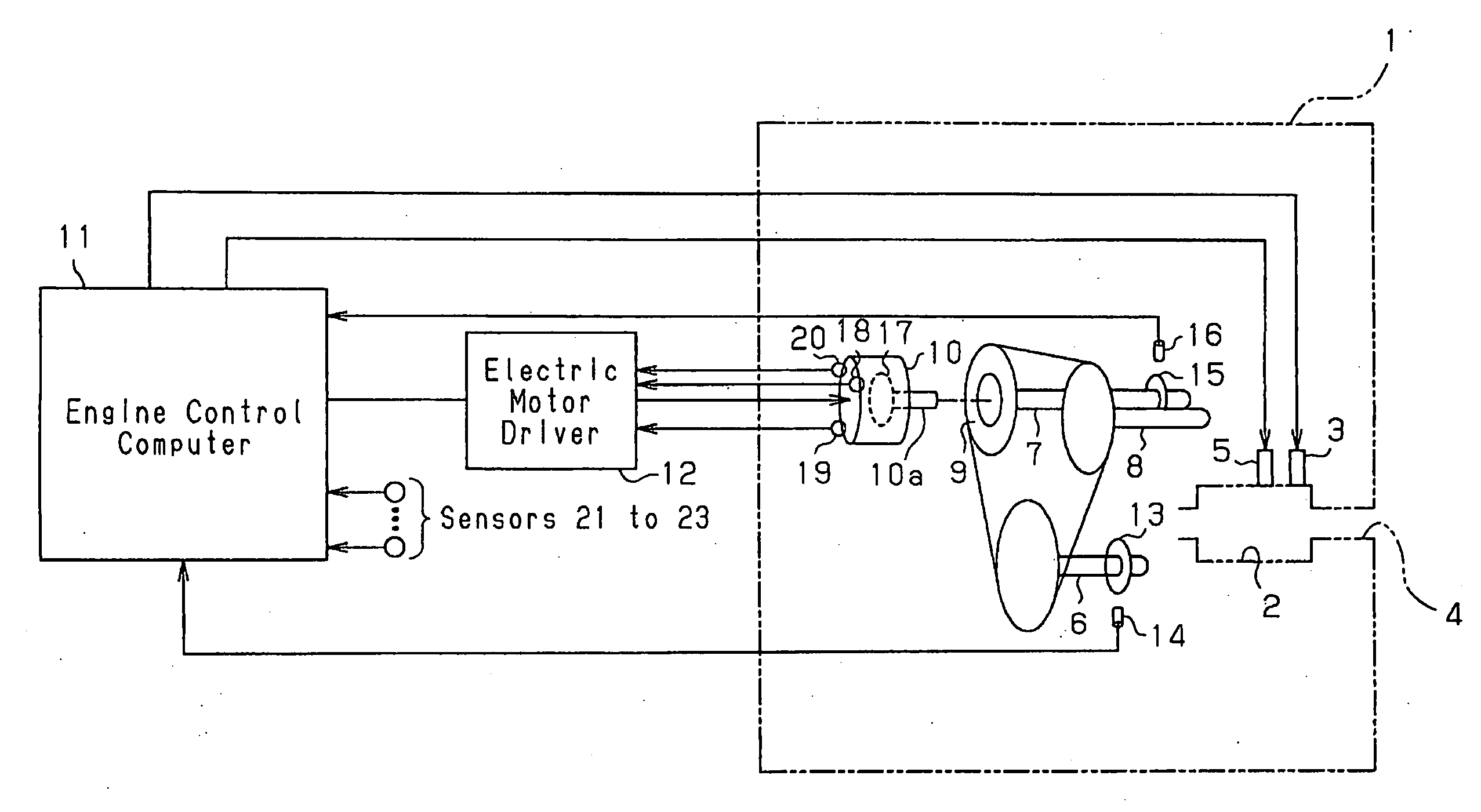
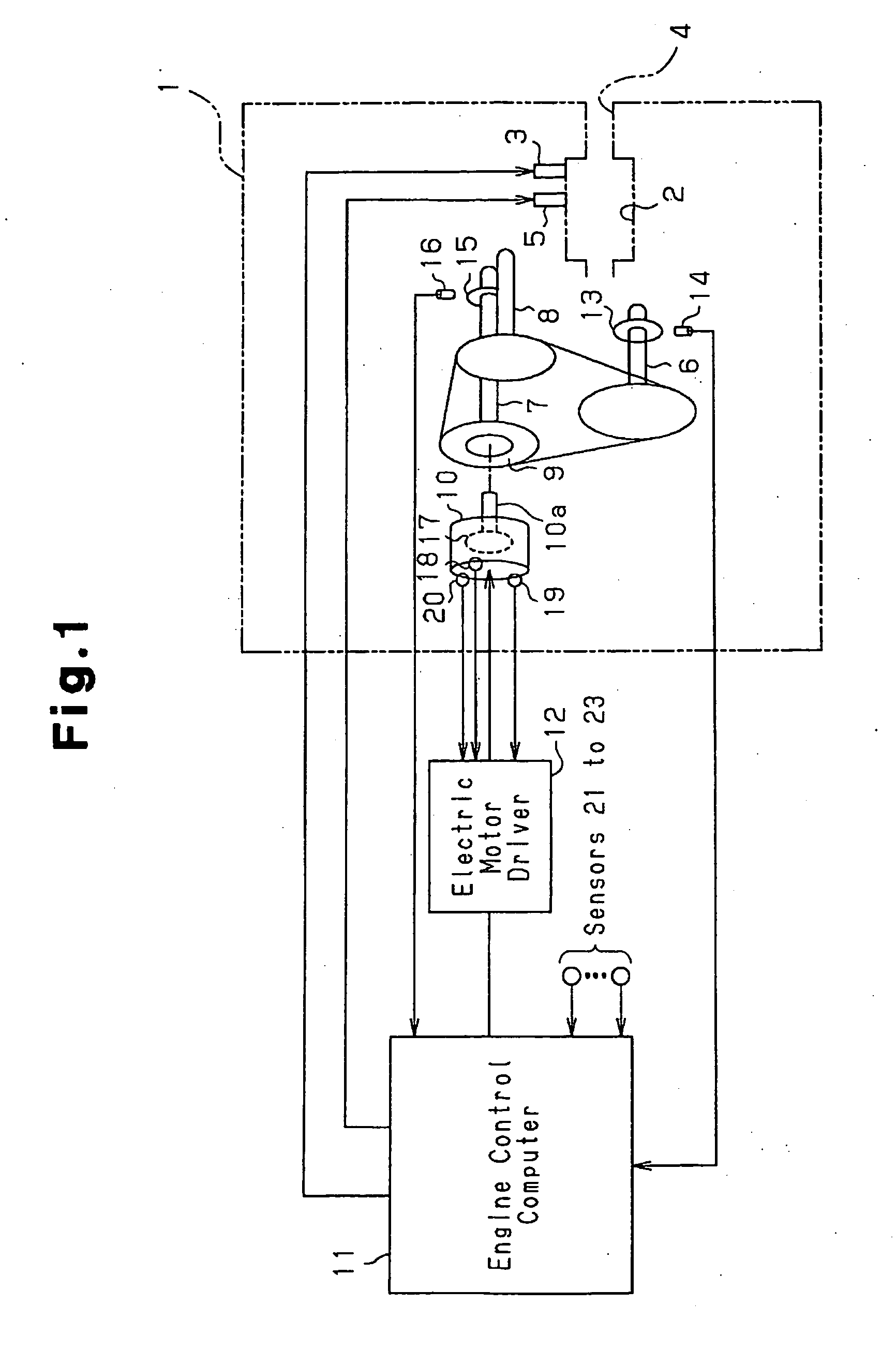
[0028] As shown in FIG. 1, the engine 1 has cylinders and combustion chambers 2 (only one is shown). Each combustion chamber 2 is defined in one of the cylinders. The engine 1 also has fuel injection valves 3, ignition plugs 5, intake valves, and exhaust valves, each corresponding to one of the combustion chambers 2. In the following, only one set of a combustion chamber 2, an injection valve 3, an ignition plug 5, an intake valve, and an exhaust valve will mainly be discussed as representing all the combustion chambers 2, the injection valves 3, the ignition plugs 5, the intake valves, and the exhaust valves.

[0029] The fuel injection valve 3 injects fuel into the combustion chamber 2, and air is drawn into the combustion chamber 2 form an intake passage 4. The air-fuel mixture is ignited by the ignition plug 5. When such ignition...

second embodiment

[0077] A second embodiment of this invention will now be described referring to FIGS. 8 through 10.

[0078] In this embodiment, an emergency operation of the engine 1 is performed as a control process for controlling the engine 1 based on the rotation pulse train from the motor driver 12 when the crank position sensor 14 malfunctions.

[0079]FIG. 8 is a flowchart illustrating an engine control routine according to this embodiment. The engine control routine is executed as an interrupt by the engine control computer 11, for example, at predetermined time intervals.

[0080] In the engine control routine, if it is determined that the crank position sensor 14 is not malfunctioning (NO at S601), the control process for controlling the normally functioning engine 1 is executed using the crank angle signal from the crank position sensor 14 at every advancement of 30° CA (S602). As such a normal control, the control process for the fuel injection control based on the flowcharts shown in FIGS. ...


PUM


Abstract

A control apparatus for an internal combustion engine includes a crankshaft, a camshaft for actuating an intake valve of the engine, a crank position sensor that outputs a crank signal every time the crankshaft rotates 10° of crank angle, an electric motor that is coupled to the camshaft, and an engine control computer that, based on the crank signal, controls the engine every time the crankshaft rotates 30° of crank angle. The motor includes a rotor and three rotation sensors. Each sensor outputs a signal corresponding to induced voltage generated by rotation of the rotor. The computer controls the rotating motor based on the signals from the rotation sensors. When the crank position sensor malfunctions, the computer controls the engine every time the crankshaft rotates 30° of crank angle based not on the crank signal but on a rotation pulse train generated based on the signals from the rotation sensors.

Description

BACKGROUND OF THE INVENTION [0001] The present invention relates to a control apparatus and a method for an internal combustion engine. [0002] A typical internal combustion engine such as an automobile engine has a crank position sensor that outputs a crank signal every time the engine output shaft, or the crankshaft, rotates a predetermined crank angle, for example, 10° CA. Based on the crank signal from the crank position sensor, control processes for operating the engine such as a fuel injection control and an ignition timing control are executed every time the crankshaft rotates, for example, 30° CA. [0003] When the fuel injection control and the ignition timing control are executed, a cylinder in which fuel injection and ignition should be executed must be distinguished. Accordingly, a process for distinguishing cylinders needs to be executed. To execute such a cylinder distinguishing control, a typical internal combustion engine is provided with a cam position sensor that outp...

Claims


Application Information

Patent Timeline
Patent Type & Authority Applications(United States)
IPC IPC(8): G06F19/00G06F17/00F02D13/02F02D45/00
CPCF01L1/34F01L1/352F01L2800/00F01L2800/11F01L2820/032F02D41/009F02D41/222Y02T10/40
Inventor NAKAMURA, MUNENORI
Owner TOYOTA JIDOSHA KK
Why Eureka
Try Eureka