Thin-film solar cell

Inactive Publication Date: 2006-08-17
SOLIBRO RES AB
View PDF2 Cites 104 Cited by
  • Summary
  • Abstract
  • Description
  • Claims
  • Application Information

AI Technical Summary

Benefits of technology

[0017] One object of the invention is to reduce the number of process steps for the m

Problems solved by technology

It fulfils many of the requirements mentioned above but can not be produced at such low cost that electricity generation in large scale is cost effective.
It also requires relatively large amount of energy in the production, which is an environmental disadvantage.
They offer a potential of substantial cost reductions but have, in general, lower conversion efficiencies and less good durability.
To fabricate the solar cell with chemical wet process steps mixed with sputtering makes the solar cell

Method used


Image

  • Thin-film solar cell
  • Thin-film solar cell
  • Thin-film solar cell

Examples


Embodiment Construction

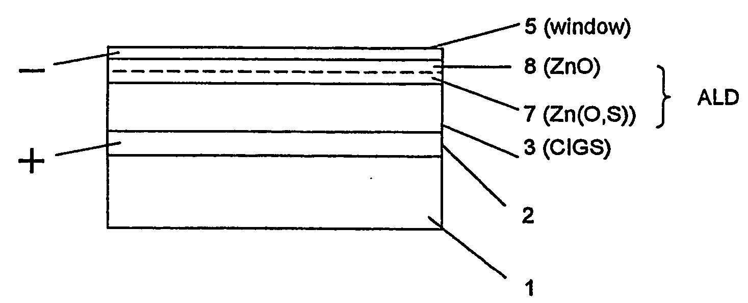
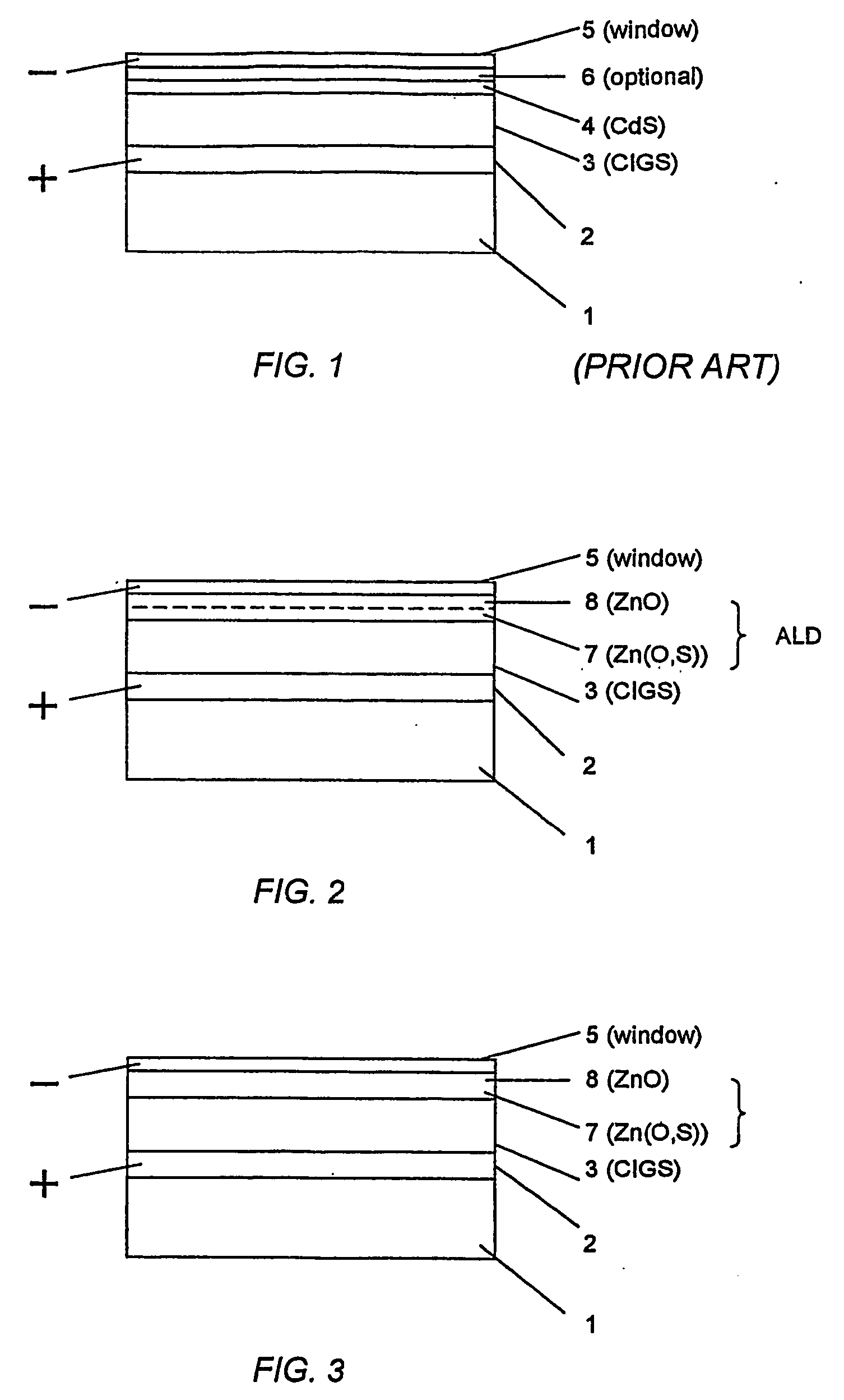
[0031] A CIGS-cell in accordance with the present invention is shown in FIG. 2. It comprises the usual glass substrate 1, the back contact layer 2 of molybdenum, the CIGS-layer 3 and the window layer 5. The usual CdS-buffer layer is replaced with two buffer layers, a first buffer layer containing Zn(O,S) deposited on the CIGS-layer and a second buffer layer 8 deposited on the first one and containing ZnO.

[0032] This is done in one process step in accordance with the invention. At first the Zn(O,S)-layer is deposited by atomic layer deposition (ALD) and immediately following this the ZnO-layer is deposited by A / D in the same process chamber. In effect, it can be considered that the two layers are replaced with one single layer of Zn(O,S), where no sulphur is added during the latter part of the deposition.

[0033] It is the inventive ALD deposition in the same chamber that makes possible the combination of a Zn(O,S)-layer and a ZnO-layer.

[0034] The function of the Zn(O,S)-layer is to...


PUM


Abstract

The present invention relates to thin-film solar cells of the CIGS-type. A characteristic feature of the invention is the use of two integrally formed buffer layers, a first ALD Zn(O,S) buffer layer (7) on top of the CIGS-layer (3) and a second ALD ZnO-buffer layer (8) on top of the first (7) buffer layer. Both buffer layers are deposited in the same process step using ALD (atom layer deposition). The invention also relates to a method of producing the cell and a process line for manufacturing of the cell structure.

Description

TECHNICAL AREA [0001] The present invention relates to a thin-film solar cell without cadmium, to a method and production line for manufacturing such cells. BACKGROUND OF THE INVENTION [0002] Solar cells provide a means to produce electric power with minimal environmental impact because it is a renewable technology. In order to become a commercial success the solar cells need to be efficient, to have low cost, to be durable, and not add other environmental problems. [0003] Today's dominant solar cell technology is based on crystalline silicon. It fulfils many of the requirements mentioned above but can not be produced at such low cost that electricity generation in large scale is cost effective. It also requires relatively large amount of energy in the production, which is an environmental disadvantage. [0004] Solar cells based on thin film technologies have been developed. They offer a potential of substantial cost reductions but have, in general, lower conversion efficiencies and ...

Claims


Application Information

Patent Timeline
IPC IPC(8): H01L31/00H01LH01L21/363H01L31/032H01L31/0336H01L31/042H01L31/0749
CPCH01L31/0322Y02E10/541H01L31/0749Y02P70/50
Inventor PLATZER BJORKMAN, CHARLOTTEKESSLER, JOHNSTOIT, LARS
Owner SOLIBRO RES AB
Why Eureka
Try Eureka