Hydrogen station, method of charging hydrogen, and vehicle

a hydrogen station and hydrogen technology, applied in the direction of vehicle heating/cooling devices, packaging, liquid transfer devices, etc., can solve the problems of large hydrogen tank, complex structure of hydrogen tanks, and high time requirements for hydrogen charging, so as to shorten the time for hydrogen charging and efficiently cool the radiator

Inactive Publication Date: 2006-08-17
TOYOTA IND CORP +1
View PDF6 Cites 20 Cited by
  • Summary
  • Abstract
  • Description
  • Claims
  • Application Information

AI Technical Summary

Benefits of technology

[0011] A first object of the present invention is to provide a hydrogen station and a method for charging hydrogen that optimally cools a hydrogen tank and shortens the time for charging hydrogen. A second object of the present invention is to provide a vehicle that efficiently cools the radiator when charging hydrogen at a hydrogen station.

Problems solved by technology

Otherwise, much time becomes necessary for the charging of hydrogen.
Thus, the structure of the hydrogen tank becomes complex and the hydrogen tank becomes large.
), the heat generated by the hydrogen adsorption alloy and the heat generated by the compression of the hydrogen gas cannot be sufficiently released by just cooling the heat medium with a normal vehicle radiator and fan.
However, to use a fan capable of producing such current velocity in a fuel cell automobile, a large installation space is required.
Further, the fan has surplus capability at times other than hydrogen charging.
Further, when charging hydrogen, the connection of the heat medium circulation passage to the heat medium coolant passage is burdensome.

Method used


Image

  • Hydrogen station, method of charging hydrogen, and vehicle
  • Hydrogen station, method of charging hydrogen, and vehicle
  • Hydrogen station, method of charging hydrogen, and vehicle

Examples


first embodiment

[0023] A first embodiment of the present invention will now be described with reference to FIGS. 1 and 2.

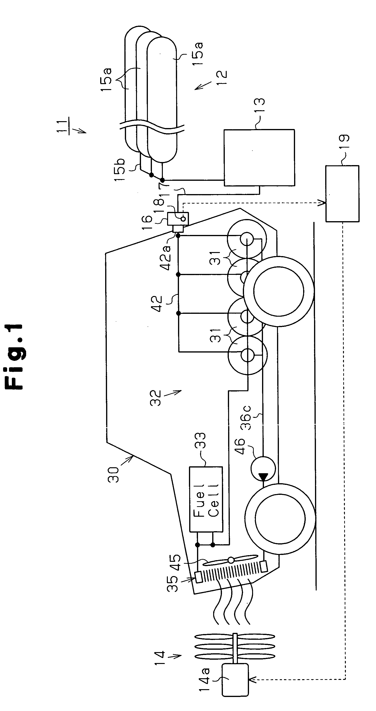
[0024] As shown in FIG. 1, a hydrogen station 11 includes gas storage equipment 12 for storing hydrogen gas, a dispenser (charger) 13 for charging hydrogen gas supplied from the gas storage equipment 12 into a plurality of hydrogen tanks 31 installed in a vehicle 30, and a blower 14. In FIG. 1, the ratio between the sizes of the vehicle 30, the gas storage equipment 12, the dispenser 13, the blower 14 and the like differs from actual size.

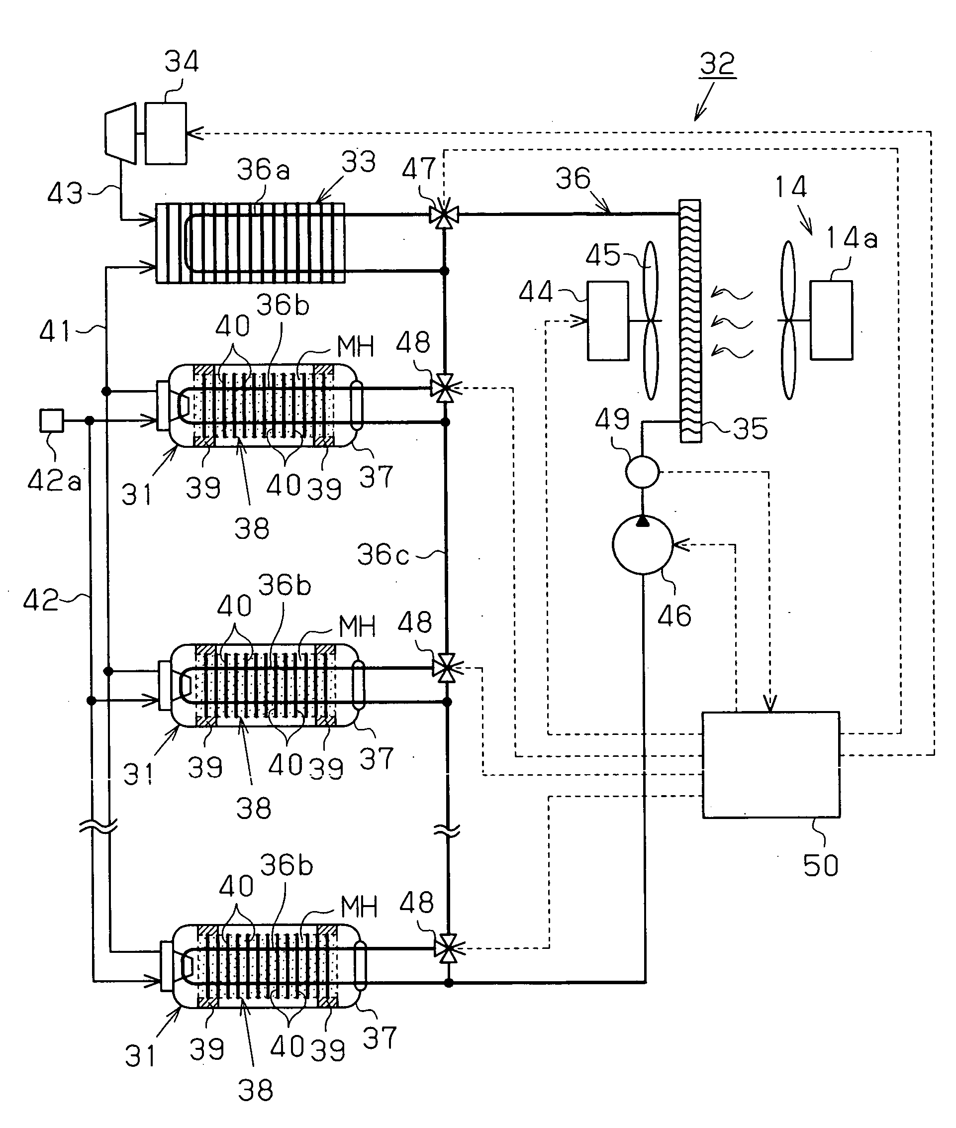
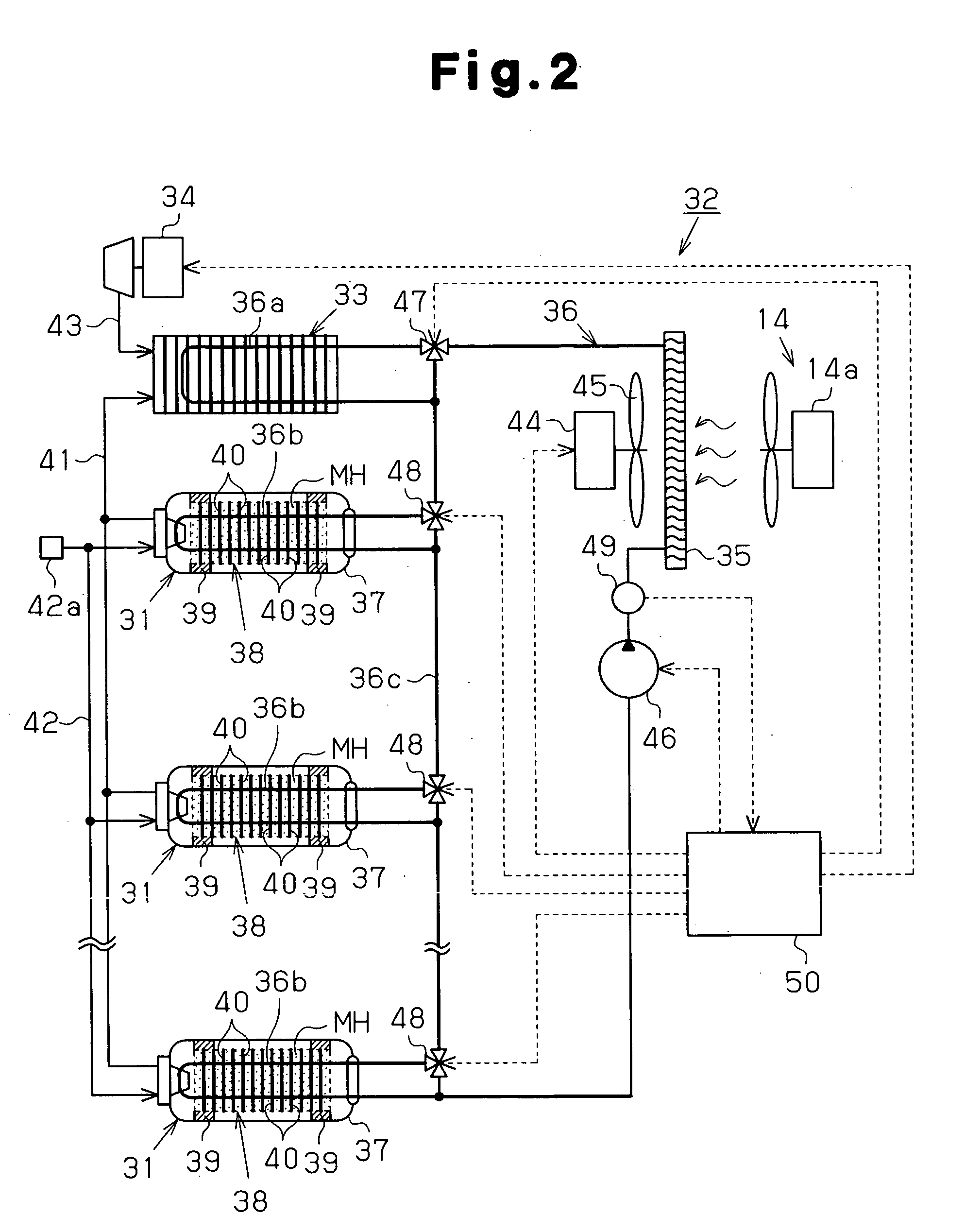
[0025] The vehicle 30 is a fuel cell automobile, of which the drive source is a fuel cell, and includes a fuel cell system 32. As shown in FIG. 2, the fuel cell system 32 includes the hydrogen tanks 31, a fuel cell 33, a compressor 34, and a radiator 35. A heat medium flow passage 36 connects the hydrogen tanks 31, the fuel cell 33, and the radiator 35. There are four hydrogen tanks 31 as shown in FIG. 1, but only three hydrogen tanks 31 are s...

second embodiment

[0054] A second embodiment of the present invention will now be described with reference to FIG. 3 focusing on the differences from the first embodiment. Components that are the same as the first embodiment are denoted with the same reference numbers and will not be described in detail. In the present embodiment, the hydrogen station 11 includes a cooling device 20, and the blower 14 blows air, which is cooled in the cooling device 20 to a temperature lower than the ambient temperature, towards the radiator 35.

[0055] As shown in FIG. 3, the cooling device 20 is arranged between the vehicle parking area of the hydrogen station 11 and the blower 14. The cooling device 20 is an evaporator forming part of, for example, a refrigeration circuit. Other components (compressor, condenser, expansion valve, etc.) of the refrigeration circuit are not shown. A refrigeration circuit having a known configuration may be used as the refrigeration circuit. The cooling device 20 includes a pipe throu...

third embodiment

[0058] A third embodiment of the present invention will now be described with reference to FIG. 4 focusing on the differences from the first embodiment. Components that are the same as the first embodiment are denoted with the same reference numbers and will not be described in detail. The present embodiment relates to a vehicle 30 enabling efficient cooling of the radiator 35 with a fan (i.e., blower arranged in the hydrogen station 11) located outside the vehicle 30 when charging hydrogen at the hydrogen station 11. The structure of the hydrogen station 11 is the same as that in the first embodiment, and the fuel cell system installed in the vehicle 30 is the same as that in the first embodiment.

[0059] A compartment 51 equivalent to an engine room of a vehicle using an internal combustion engine as the driving source is defined at the front of the vehicle 30. The radiator 35 is arranged toward the front of the vehicle 30 in the compartment 51. A front grille 53 is integrally form...


PUM

PropertyMeasurementUnit
pressureaaaaaaaaaa
current velocityaaaaaaaaaa
temperatureaaaaaaaaaa

Abstract

A hydrogen station includes gas storage equipment for storing hydrogen, a dispenser for charging hydrogen gas supplied from the gas storage equipment into a hydrogen tank of a vehicle, and a blower. When charging hydrogen, the blower blows air towards a radiator of the vehicle parked at a predetermined vehicle parking area of the hydrogen station. The current flow of the blower is adjusted in accordance with the heat load on the radiator.

Description

BACKGROUND OF THE INVENTION [0001] The present invention relates to a hydrogen station, a method for charging hydrogen, and a vehicle, and more particularly, to a technique suitable for quickly charging hydrogen into a hydrogen tank installed in a vehicle. [0002] Recently, people have become more conscious of the need for suppressing global warming. Thus, hydrogen-fueled automobiles using hydrogen as fuel, such as fuel cell electric automobiles and hydrogen automobiles, have been developed. A typical hydrogen-fueled automobile is provided with a hydrogen tank that is charged with hydrogen gas and functions as a hydrogen supply source. [0003] The use of metal referred to as “hydrogen adsorption alloy” has been given attention as a method for storing and transporting hydrogen. Hydrogen adsorption alloy adsorbs hydrogen and becomes a hydride under certain temperature and pressure conditions and releases hydrogen when necessary under different temperature and pressure conditions. A hydr...

Claims


Application Information

Patent Timeline
Patent Type & Authority Applications(United States)
IPC IPC(8): B65B1/28B65B1/20
CPCB60H1/00257F17C2270/0184B60L11/1896B60L2240/36F17C5/06F17C11/005F17C2265/065F17C2270/0139H01M8/04201H01M2250/20Y02E60/321Y02T90/32Y02T90/34Y02E60/50F17C2201/0109F17C2201/056F17C2201/058F17C2205/0142F17C2205/0326F17C2221/012F17C2223/0123F17C2227/0157F17C2227/0309F17C2227/0313F17C2227/0388F17C2227/0397F17C2250/032F17C2250/043F17C2250/0439F17C2250/0631F17C2260/025F17C2270/0168B60H1/00392B60L50/71Y02E60/32Y02T90/40
Inventor KUBO, HIDEHITOISOGAI, YOSHIHIROMORI, DAIGORO
Owner TOYOTA IND CORP
Why Eureka
Try Eureka