
Control apparatus for a fire pump, operation display apparatus for a fire pump and operation mode control apparatus for a fire pump

a control apparatus and fire pump technology, applied in the direction of pump control, application, positive displacement liquid engine, etc., can solve the problems of remote control system operation efficiency problem, inability to grasp the operation condition of the pump in real time, and inability to communicate freely between the communication worker and the nozzle operator in an extremely noisy scene of fir

Inactive Publication Date: 2006-08-17
YOSHIDA KENICHI
View PDF1 Cites 50 Cited by
  • Summary
  • Abstract
  • Description
  • Claims
  • Application Information

AI Technical Summary

Benefits of technology

[0021] Accordingly, a first object according to the present invention is to provide a control apparatus for a fire pump, capable of not only controlling a pump remotely but also grasping the operation condition of the pump in real time, and having excellent operation controllability and information transfer capability.
[0022] A second object according to the present invention is to provide an operation display apparatus for a fire pump, capable of carrying out various control and display operations, and having excellent controllability and safety.
[0023] A third object according to the present invention is to provide a operation mode control apparatus for a fire pump having an automatic relay water supply mode, and capable of preventing the setting of a mode during a mode switching operation.

Problems solved by technology

Hei 8-252339, the communication worker is needed in addition to the nozzle operator, and the communication between the communication worker and the nozzle operator in an extremely noisy scene of a fire cannot be made freely in some cases.
Therefore, this remote control system has a problem concerning an operation efficiency thereof.
In the remote control system disclosed in the above-mentioned Japanese Patent Unexamined Publication No. Hei. 5-231172, the nozzle operator can control the pump by himself but he cannot grasp the operation condition of a pump in real time since there is not a response to the nozzle operator's operation.
Therefore, this remote control system has a problem concerning the capability of the system of transferring information to the nozzle operator.
Therefore, pointers of the meters were not stabilized due to the pulsation of a discharge pressure, etc., and the reading of a value indicated by the pointer was not easily done.
Especially, when a controller is provided in a position away from a pump body so that a remote control operation can be carried out, a judgement based on a sound of the engine could not be made.
Also, it was impossible to accurately grasp the condition of the pump and control the pump remotely.
On the other hand, it is hard to say that consideration is given to the switch and keys provided on the operation display unit, with respect to the controllability and an erroneous operation thereof.
Further, in a case where a pump is formed so that, every time a mode switching switch is pressed for carrying out such a operation mode switching operation, a operation mode is switched and fixed to a switched mode, when an input water pressure of not lower than a predetermined level is detected by a water pressure sensor, an operation mode cannot be switched to an automatic relay water supply mode onward in some cases.
Therefore, when an input water pressure is not lower than a starting pressure, an inconvenience occurs, i.e., the moment an actual mode is switched to an automatic relay water supply mode during a operation mode switching operation, the engine is started to cause a relay water supply operation to be started and fixed, and the mode cannot be shifted to any further mode.
In such a case, modes beyond the automatic relay water supply mode cannot be selected.

Method used


Image

  • Control apparatus for a fire pump, operation display apparatus for a fire pump and operation mode control apparatus for a fire pump
  • Control apparatus for a fire pump, operation display apparatus for a fire pump and operation mode control apparatus for a fire pump
  • Control apparatus for a fire pump, operation display apparatus for a fire pump and operation mode control apparatus for a fire pump

Examples


Embodiment Construction

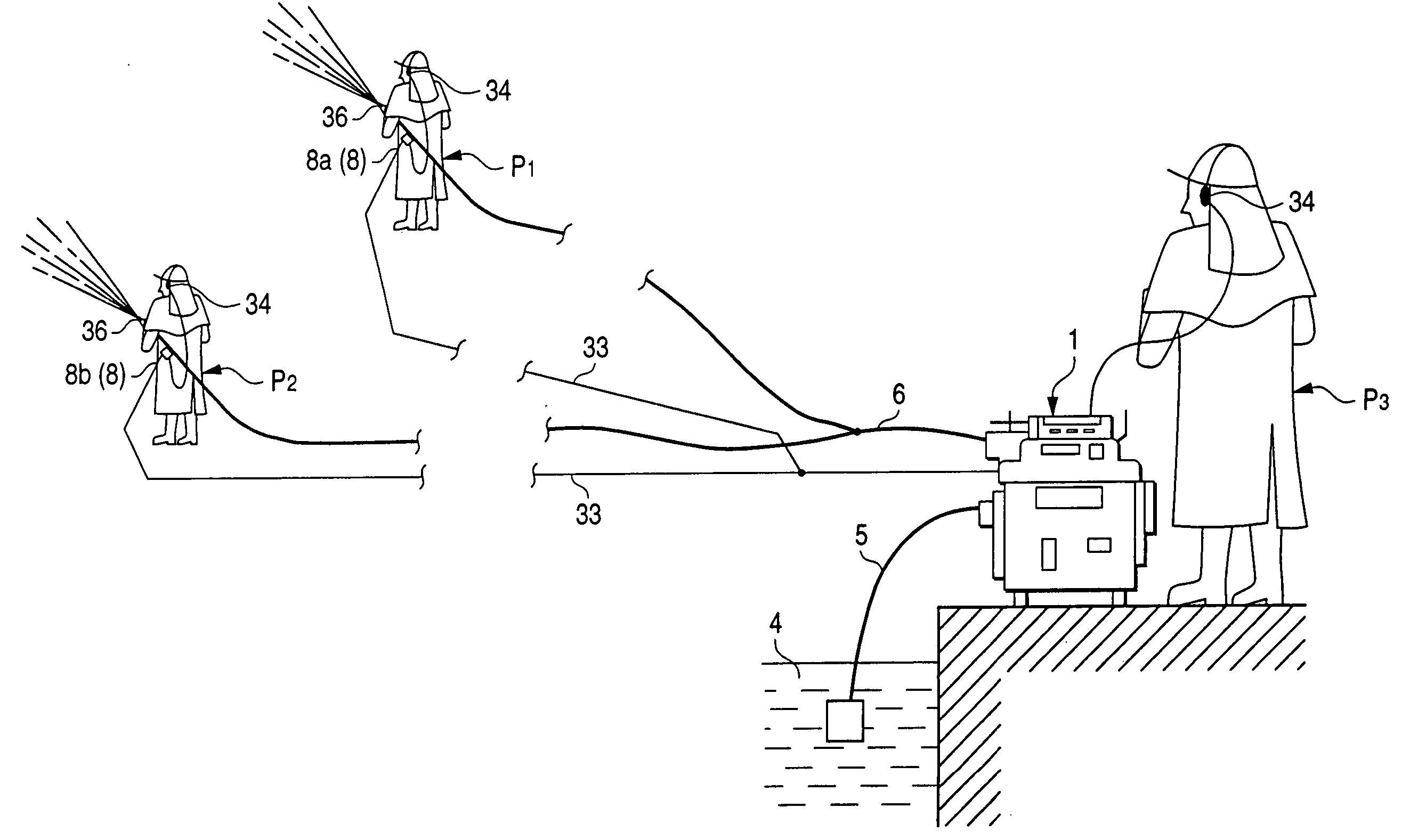
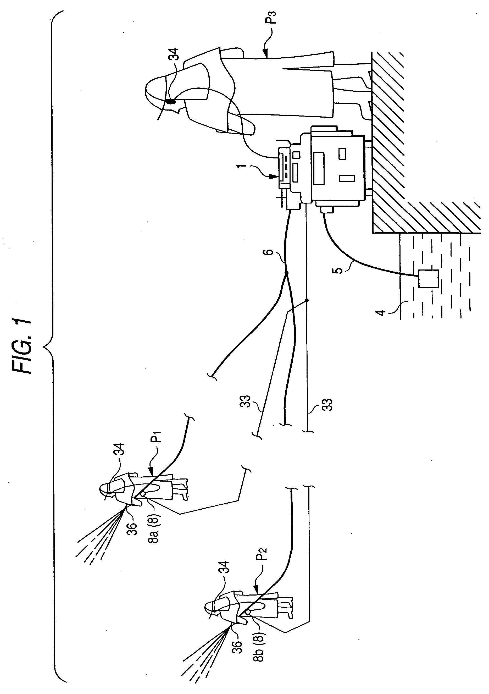
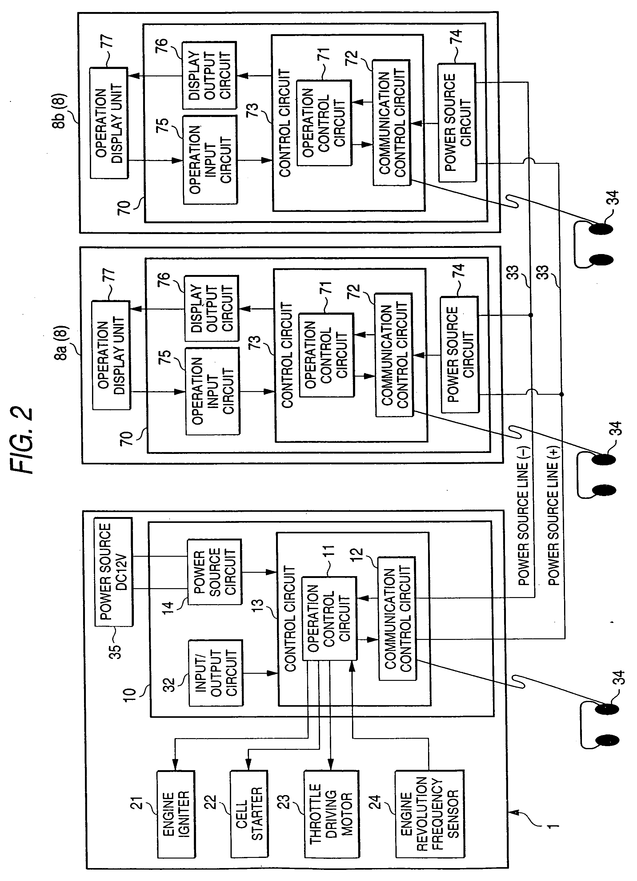
[0056] A mode of embodiment of the present invention will now be described in detail on the basis of the drawings. FIG. 1 illustrates a general construction of a fire pump control system using a nozzle control unit of an embodiment according to the present invention. FIG. 2 illustrates the construction of a control system in the system of FIG. 1.

[0057] In this system, a fire pump body of a fire pump 1 and nozzle control units 8 (8a, 8b) are connected together via power source lines 33 so as to not only control the pump 1 remotely on the side of the nozzle control unit 8 but also display the condition thereof. In this case, the supplying of electric power via the power source lines 33 is done with respect to the nozzle control unit 8 with a weight load of a battery and the consumption of the same taken into consideration. The transmission of signals between the pump 1 and nozzle control unit 8 is carried out by digital cable power line communication made via the power source lines 3...


PUM


Abstract

In a fire pump adapted to force out the water, which is pumped from a water source, from a nozzle provided at a front end portion of a delivery hose, a nozzle control unit 8 adapted to control the fire pump remotely is provided in the vicinity of the nozzle. The nozzle control unit 8 is connected to a body of the fire pump 1 by power source lines 33. On the nozzle control unit 8, a control instruction unit for instructing an operating mode of the pump 1, and a numerical value display unit for displaying the operation condition of the fire pump are provided. The transmitting and receiving of an operation control signal and a condition display signal are done between the pump 1 and nozzle control unit 8 by power line communication via the power source lines 33, whereby the operation condition of the pump 1 is feedback displayed in real time in response to a control operation of a nozzle operator.

Description

BACKGROUND OF THE INVENTION [0001] 1. Field of the Invention [0002] This invention relates to fire pump control techniques, and more particularly to a control apparatus for a fire pump. In a fire pump having a fire pomp body and a nozzle connected to the pump body via a delivery horse, such a control apparatus is formed at a side of the nozzle so as to enable the controlling of an operation of a fire pump body and the displaying of the operation condition of the same to be done in real time. [0003] The present invention also relates to an operation display unit for a fire pump, and more particularly to an operation display apparatus for a fire pump which enable not only the controlling of an operation of the fire pump and the displaying of the operation condition of the fire pump. [0004] Further, the present invention relates to a operation mode control apparatus for a fire pump, and more particularly to a operation mode control apparatus for a fire pump having an automatic relay wa...

Claims


Application Information

Patent Timeline
IPC IPC(8): A62C35/00
CPCA62C25/00A62C31/02A62C35/026F04B17/05F04B49/02F04B49/065
Inventor YOSHIDA, KENICHI
Owner YOSHIDA KENICHI
Learn More