Method of refining wood chips or pulp in a high consistency conical disc refiner

a technology of conical discs and refining machines, which is applied in the field of wood pulp refining, can solve the problems of affecting the consistency of the single loop control scheme, the effect of specific energy, refining intensity and pulp quality, and the inability to control the consistency of the single loop, so as to achieve the effect of avoiding increasing the consistency at the inlet of the refiner, and avoiding the plugging of the pla

Active Publication Date: 2006-08-17
FPINNOVATIONS INC
View PDF11 Cites 4 Cited by
  • Summary
  • Abstract
  • Description
  • Claims
  • Application Information

AI Technical Summary

Benefits of technology

[0028] In accordance with the invention, consistency at the inlet of the refiner can be increased while maintaining the discharge consistency (blow line consistency) constant. As a result the average refining consistency becomes higher while the consistency of the pulp at the periphery of the plates remains constant, thus avoiding plugging of the plates. The refiner motor load will also increase but can easily be brought back to its original value through an increase in the plate gaps. The result is an operation at the same motor load and specific energy but higher average refini

Problems solved by technology

The single loop consistency control scheme of the prior art has many limitations; one of them is its effect on specific energy.
Another limitation of the single loop consistency control scheme is that the same discharge consistency can be obtained with different distributions of dilution water flows among in-feed, flat zone and conical zone dilutions.
On the other hand, refining intensity and pulp quality will be different at these different distributions, a source of problems if not properly recognized.
However, in this previous U.S. patent no distinction has been made in the use of dilution water added before or during refining for consistency control.
The same issue of quality loss due to produ

Method used


Image

  • Method of refining wood chips or pulp in a high consistency conical disc refiner
  • Method of refining wood chips or pulp in a high consistency conical disc refiner
  • Method of refining wood chips or pulp in a high consistency conical disc refiner

Examples


Embodiment Construction

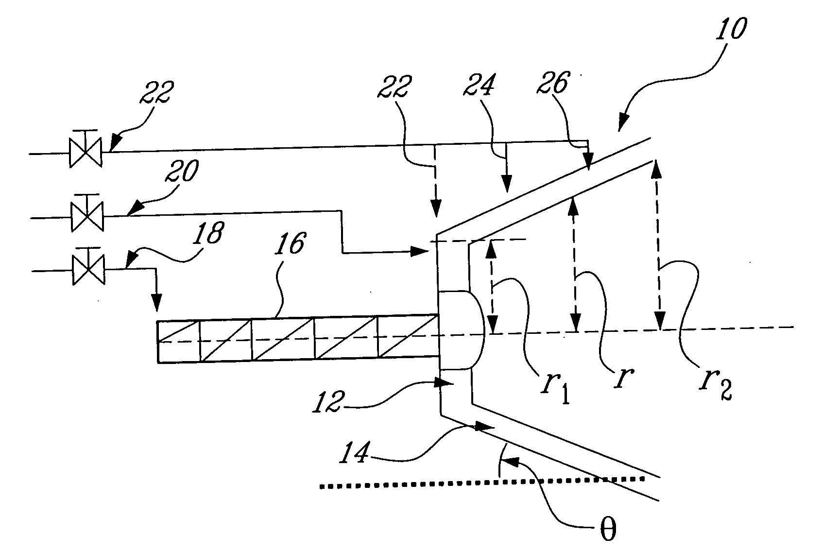
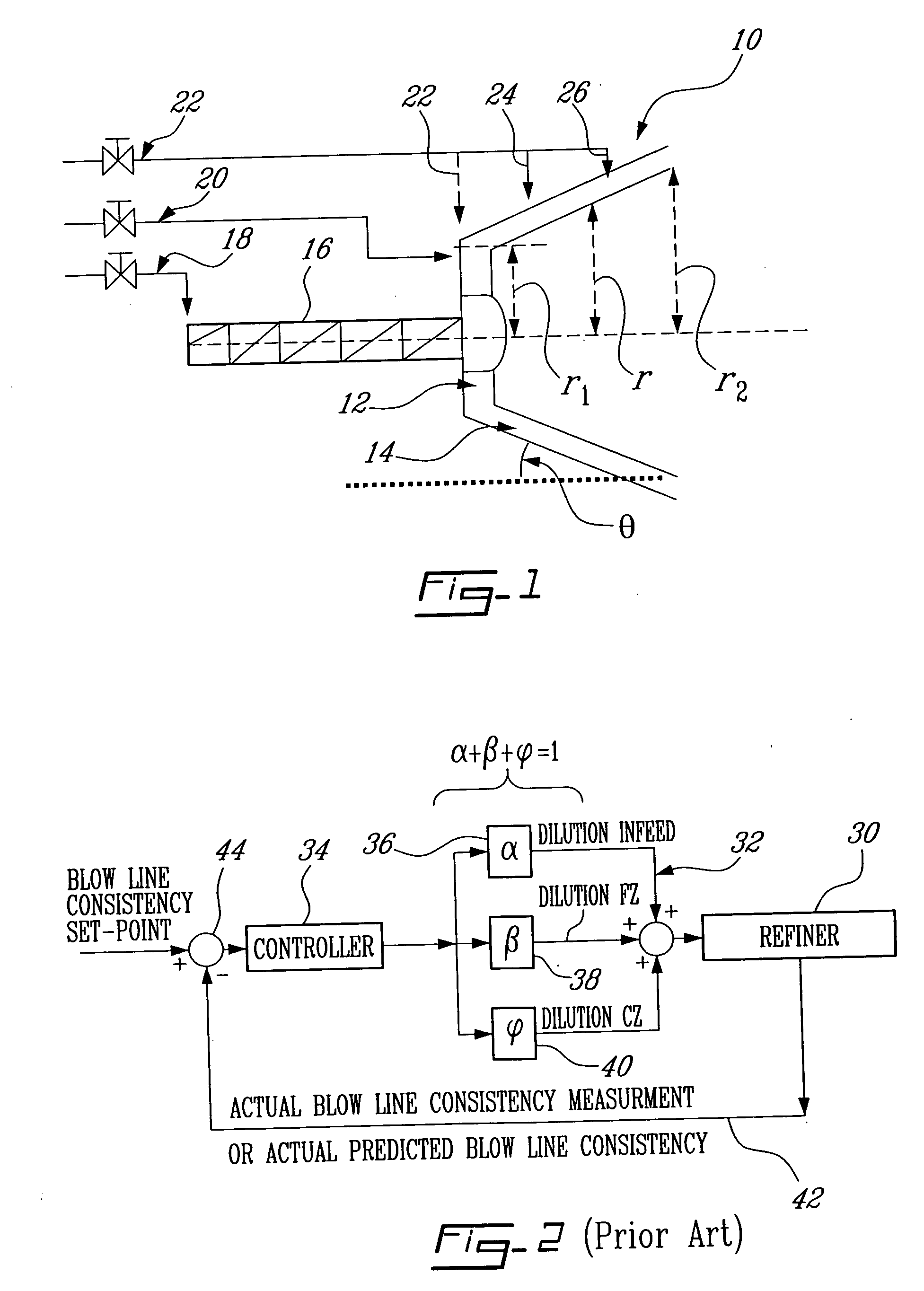
[0033] With further reference to FIG. 1, a conical refiner 10 is illustrated schematically. Conical refiner 10 has a gap flat zone 12, and a gap conical zone 14.

[0034] Conical zone 14 may be considered to comprise a multiplicity of zones of different radii, for example at radii r1, r and r2 in FIG. 1. Conical zone 14 has an angle of slope θ.

[0035] Refiner 10 has an inlet 16 for chips or pulp to be refined, and dilution infeed line 18, dilution flat zone line 20 and dilution conical zone line 22 for feed of dilution water to inlet 16, flat zone 12 and conical zone 14, respectively. Line 22 may have branch line 24, 26 and 28 for feeding dilution water in line 22 to different parts of conical zone 14. Thus, for example, branch line 24 feeds dilution water to an upstream or inlet end of conical zone 14.

[0036] With further reference to FIG. 2, there is shown schematically a prior art refining system in which a refiner 30 has a dilution unit 32 and a controller 34.

[0037] The dilution ...


PUM

PropertyMeasurementUnit
Flow rateaaaaaaaaaa
Heataaaaaaaaaa
Residence timeaaaaaaaaaa

Abstract

A method is proposed for improving pulp quality at high production rates on conical disc refiners. It permits a reduction in refining intensity by enabling fibre residence time to increase by increasing consistency, while avoiding the problem of plate plugging normally associated with high discharge consistency. In practice, inlet consistency is increased by the in-feed dilution, flat zone dilution or both, but without allowing the discharge consistency to rise. Instead, the discharge consistency is controlled at a fixed optimum value by the addition of dilution water within the conical zone. The result is that residence time is increased, and refining intensity decreased, by raising the consistency in the inner region of the refining zone, while avoiding the plate plugging caused by excessive consistency in the outer region of the refining zone.

Description

CROSS-REFERENCE TO RELATED APPLICATIONS [0001] This application is related to U.S. Provisional Application Ser. No. 60 / 651,653 filed Feb. 11, 2005 and the benefit under 35 USC1 19(e) of such U.S. Provisional Application is claimed.BACKGROUND OF THE INVENTION [0002] 1. Field of the Invention [0003] This invention relates to a method of refining wood pulp; more especially the invention relates to such a method in which pulp consistency in the refiner is adjusted by controlled addition of dilution water to the refiner. [0004] In a preferred embodiment, the present invention relates to a method for controlling TMP (thermomechanical pulp) refiners by adjustment of the refining intensity. Pulp consistencies in the refiner are controlled and adjusted to achieve stable refining intensity and to compensate for disturbances such as the ones associated with changes in production rate. [0005] 2. Description of the Prior Art [0006] The quality of the pulp in thermomechanical pulp (TMP) refining ...

Claims


Application Information

Patent Timeline
IPC IPC(8): D21D1/30
CPCD21D1/002D21D1/20D21D1/22D21D1/38
Inventor ETTALEB, LAHOUCINEROCHE, ALAIN ANDREMILES, KEITH
Owner FPINNOVATIONS INC
Why Eureka
Try Eureka