
Method and a system for programming an industrial robot to move relative to defined positions on an object, including generation of a surface scanning program

a technology of industrial robots and programming systems, applied in the direction of programme control, electric controllers, total factory control, etc., can solve the problems of large robot accuracy, inconvenient operation, and inability to accurately program robots, etc., to achieve the effect of simplifying the calibration and programming of robots

Active Publication Date: 2006-08-17
ABB (SCHWEIZ) AG
View PDF13 Cites 128 Cited by
  • Summary
  • Abstract
  • Description
  • Claims
  • Application Information

AI Technical Summary

Benefits of technology

[0004] The object of the present invention is to provide a method and a system to simplify calibration and programming of a robot.

Problems solved by technology

However, those positions have to be corrected with regard to geometric and kinematic errors of the robot, the tool, and the work object.
Examples of such errors are deviations between the real object and the model, an error in the positioning of the robot relative to the surrounding, arm length errors, shaft attitude error, and shaft offset error of the robot.
Today, the accuracy of the robot is a huge problem when using the robots.
It is very expensive to build a high-accuracy robot, in which each component is carefully measured, and the kinematic parameters of the robot are calibrated by means of a laser measuring system.
As long as there does not exist any simple and inexpensive method for calibrating and programming industrial robots, those will only be used in companies having enough financial and personnel resources.

Method used


Image

  • Method and a system for programming an industrial robot to move relative to defined positions on an object, including generation of a surface scanning program
  • Method and a system for programming an industrial robot to move relative to defined positions on an object, including generation of a surface scanning program
  • Method and a system for programming an industrial robot to move relative to defined positions on an object, including generation of a surface scanning program

Examples


third embodiment

[0107] In one embodiment, the user shows where to place all the measuring points on the object, and the path to be followed by the robot during the measuring, by pointing on the CAD model of the object. Thereafter, a surface scanning program is automatically generated, which surface scanning program controls the movements of the robot during the measuring. In another embodiment, the user only shows the measuring points and the robot motion, necessary for performing the measuring, are automatically generated. In a third embodiment, it is enough if the operator defines which surfaces to be measured, by pointing out those surfaces on the CAD model. Thereafter the CAD system generates a surface scanning program for controlling the movements of the robot during the measuring. Besides which surfaces to be measured, the user also specifies the scanning density of the measuring. The CAD system lays out the positions of the measuring points in a raster, and later determines by means of known...

embodiment 5

[0114] In FIG. 18 the upper figure shows an object surface 120 having manually positioned measuring points, and the lower left figure shows measuring points 117 automatically generated by the surface scanning program. The figure illustrates that the automatically generated measuring points have to be kept within an uncertain zone 122. The zone 122 represents the area in which it is uncertain if the object is there or not. Within this zone no measuring points should be generated. If the sensor in any way should fail to hit the object when the measuring device is moved down towards the surface of the object, the program should include a function, which detects if the sensor has been moved too far, and which then interrupt the measuring of the measuring point. The left figure illustrates that it during measuring with an LVDT sensor also has to be margins during programming of the sensor movement in a direction towards a measuring point 117. The figure shows the uncertainty due to where...


PUM


Abstract

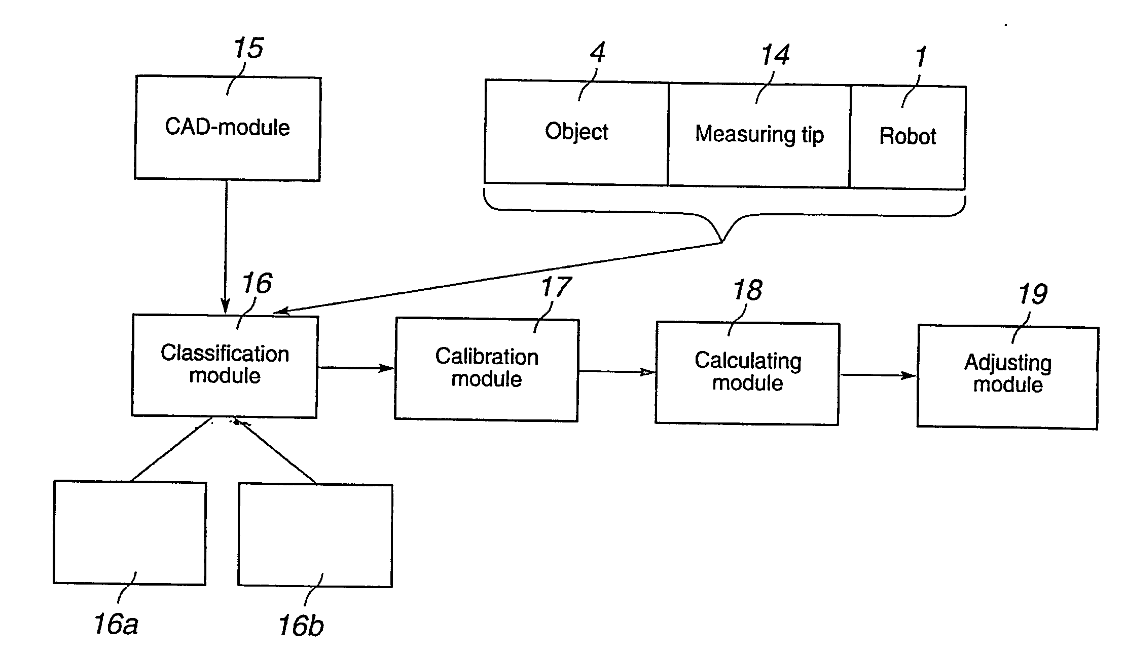
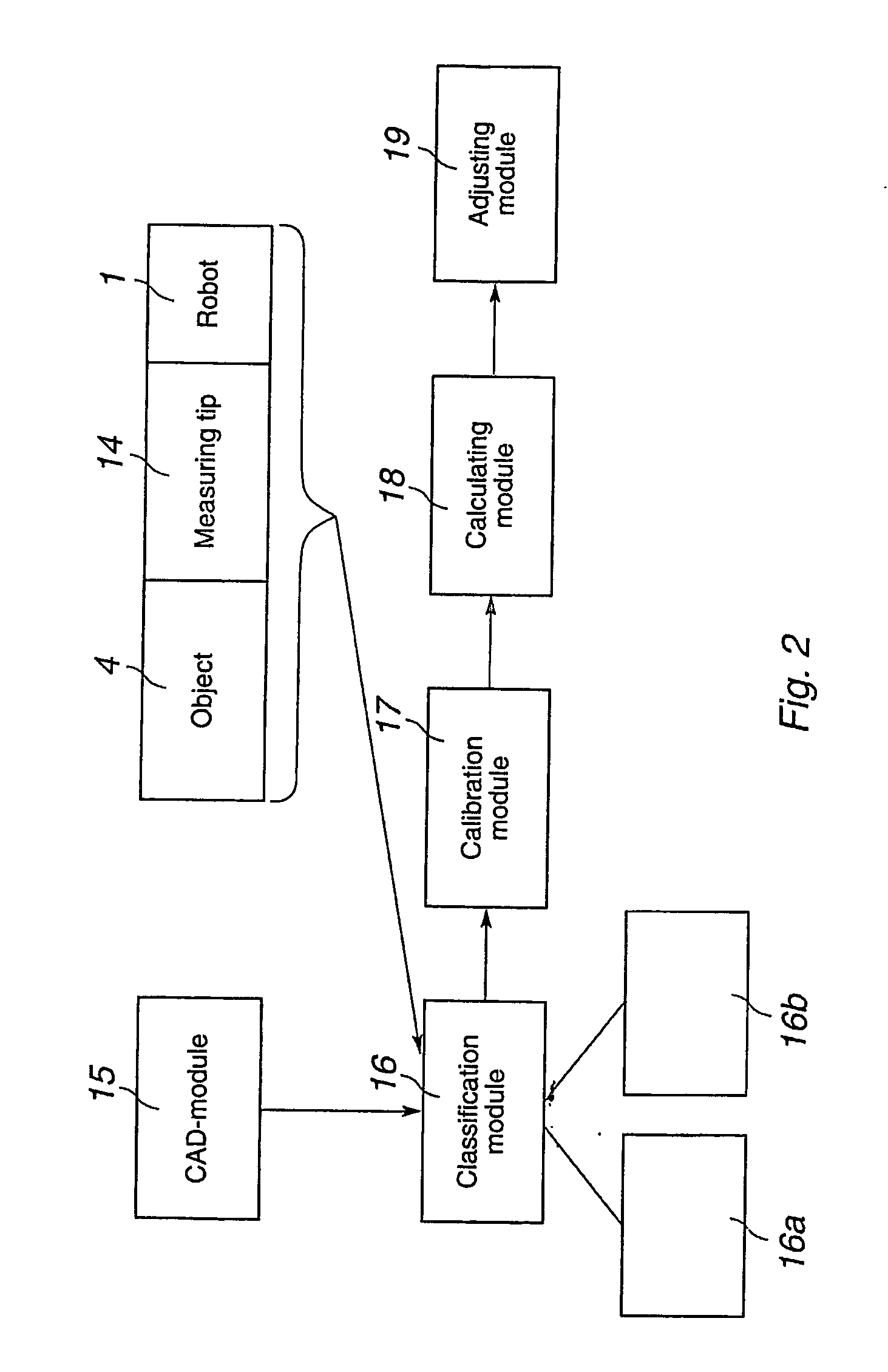
A method and a system for programming an industrial robot to move relative to defined positions on an object. The system includes a geometrical model of the object, the real object, and an industrial robot. A plurality of measuring points are generated corresponding to different points on the surface of the real object expressed in a coordinate system associated with the robot. The system further includes a calibration module arranged to determine orientation and position of the geometrical model of the object relative to the coordinate system associated with the robot, a calculating module arranged to calculate the deviation between the measuring points and corresponding points on the geometrical model, and an adjusting module arranged to adjust the defined positions based on the calculated deviations.

Description

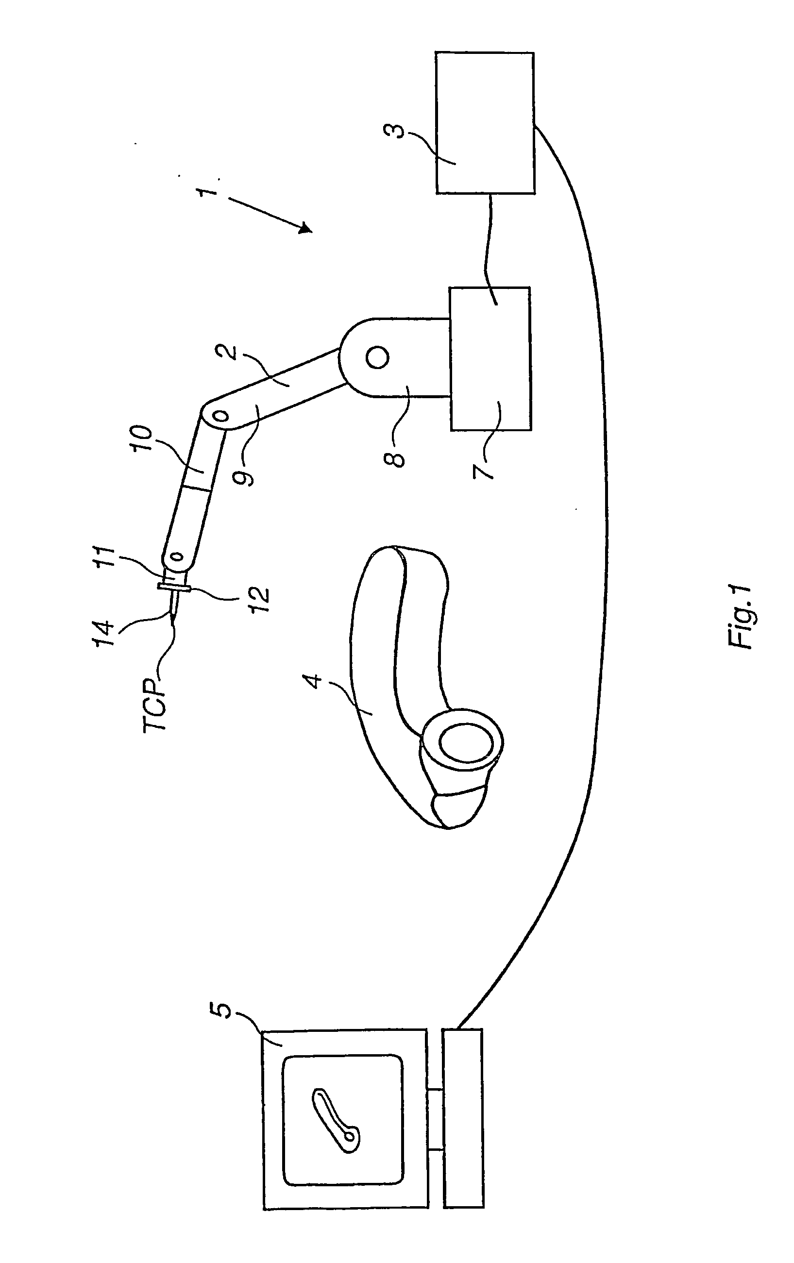
TECHNICAL AREA AND PRIOR ART [0001] The present invention relates to a method, a system, a computer program, and a computer readable medium comprising a computer program for programming an industrial robot to move relative to defined positions on an object, wherein the programming is based on a geometric model of the object. The object can either be a working object, a fixture, a grip device, or a tool. The invention is particularly useful in connection with programming of a robot path comprising a plurality of defined positions on the object, for example for painting, grinding, milling, welding, or gluing. However, the invention is also useful for programming individual positions, for example for spot welding or object gripping. [0002] It is well known technology to program an industrial robot using a CAD model of the object. The positions of the robot path are received from the CAD model. However, those positions have to be corrected with regard to geometric and kinematic errors o...

Claims


Application Information

Patent Timeline
Patent Type & Authority Applications(United States)
IPC IPC(8): B25J9/16G05B19/42G05B19/423
CPCB25J9/1671G05B19/4083G05B19/4207G05B19/425G05B2219/34135G05B2219/36504G05B2219/40564G05B2219/40581Y02P90/02
Inventor BROGARDH, TORGNY
Owner ABB (SCHWEIZ) AG
Learn More