Illuminating device

Active Publication Date: 2006-08-17
BOE TECH GRP CO LTD
View PDF3 Cites 12 Cited by
  • Summary
  • Abstract
  • Description
  • Claims
  • Application Information

AI Technical Summary

Benefits of technology

[0007] An advantage of some aspects of the invention is that it provides an illuminating device having high brightness and high usage efficiency of

Problems solved by technology

However, the optical waveguide emits light mainly in a specific direction light, rather than uniformly in all directions.
Therefore, merely increasing the refractive index of the p

Method used


Image

  • Illuminating device
  • Illuminating device
  • Illuminating device

Examples


Embodiment Construction

[0032] Hereinafter, preferred embodiments of the invention will be described with reference to the accompanying drawings.

Structure of Liquid Crystal Display Device

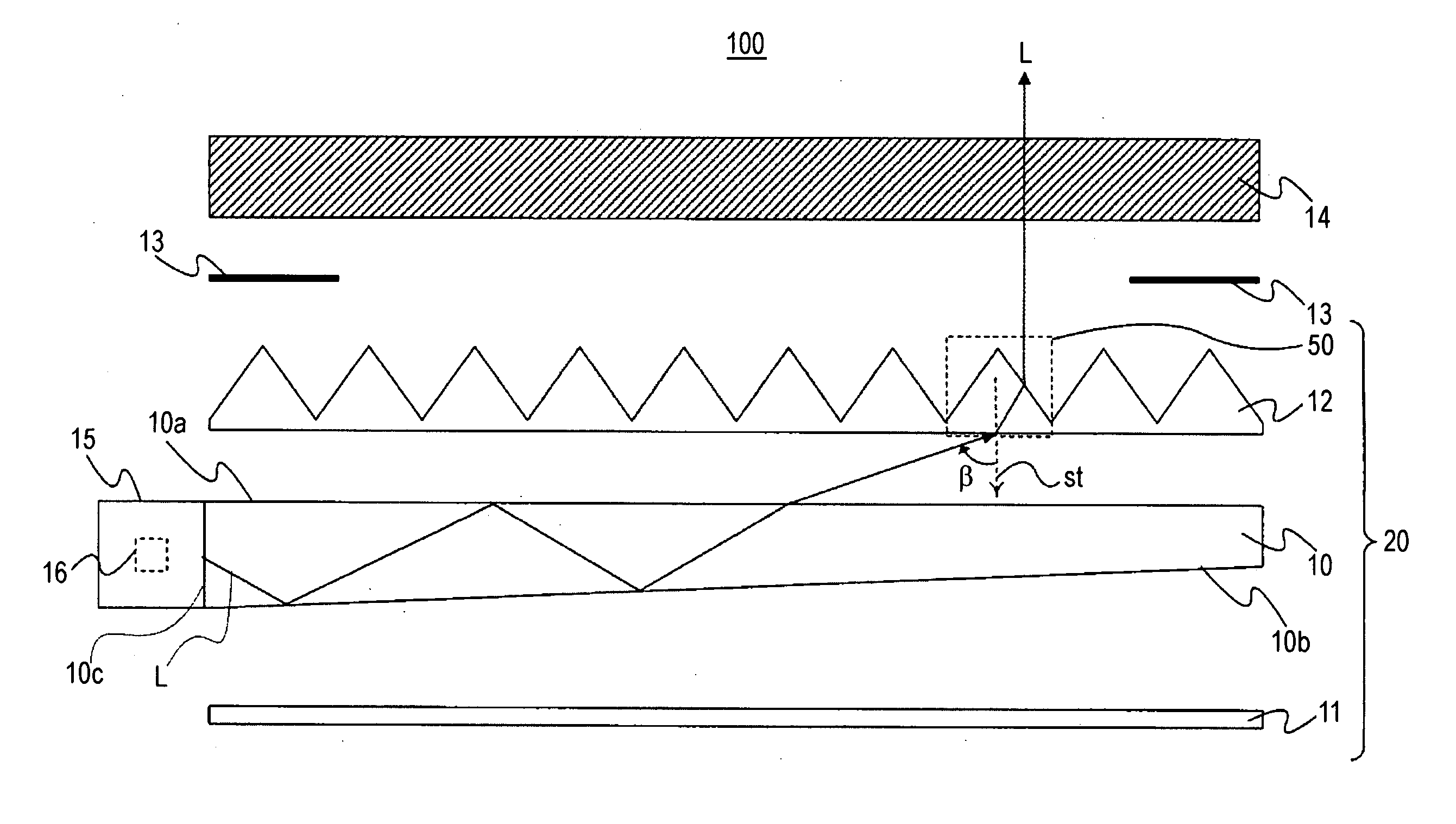
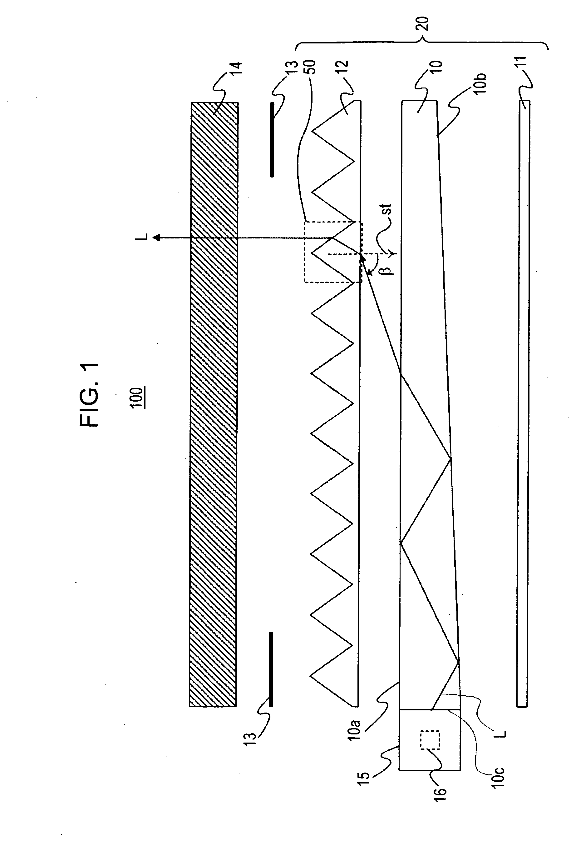
[0033]FIG. 1 shows the schematic structure of a liquid crystal display device 100 provided with an illuminating device according to the invention. In FIG. 1, an illuminating device 20 of the invention is a surface-emitting-type illuminating device used as a backlight unit, for example, in the liquid crystal display device 100. The illuminating device 20 includes an optical waveguide 10 having a light source 15 at one end, a reflective sheet 11 provided below the optical waveguide 10, and a prism sheet 12 provided above the optical waveguide 10. The illuminating device 20 is adhered to a liquid crystal panel 14 by a double-sided tape 13.

[0034] In the illuminating device 20, a light source 15 includes a plurality of LEDs 16 serving as point light sources and emits light to an end surface (hereinafter, referred to as a ‘l...


PUM


Abstract

An illuminating device includes a light source, an optical waveguide that emits light from the light source through an emission surface thereof, and a prism sheet that is provided on the emission surface side of the optical waveguide. In the illuminating device, the following relationship is established between a refractive index x of the prism sheet and an apex angle y of a prism: y=107.86x−140.43+M (−4≦M≦4).

Description

BACKGROUND [0001] 1. Technical Field [0002] The present invention relates to an illuminating device, such as a backlight unit used for, for example, a liquid crystal display device of a cellular phone. [0003] 2. Related Art [0004] A liquid crystal display device includes a backlight unit on the rear surface side of a liquid crystal display panel to perform transmissive display. In general, the backlight unit is composed of an illuminating device including a light source, an optical waveguide for emitting light from the light source to the rear surface of the liquid crystal display panel as surface light, a sheet for diffusing light emitted from the optical waveguide, and a prism sheet for condensing light. Light incident on the optical waveguide from the light source travels in the optical waveguide while repeatedly reflecting from an emission surface and a reflective surface of the optical waveguide, and is then emitted from the emission surface to the outside. [0005] The light emi...

Claims


Application Information

Patent Timeline
IPC IPC(8): F21V7/04
CPCG02B6/0046G02B6/0048G02B6/0051G02B6/0053
Inventor ONISHI, YASUNORI
Owner BOE TECH GRP CO LTD
Why Eureka
Try Eureka