Robot wrist comprising a drive unit incorporated in a tilt

Inactive Publication Date: 2006-08-17
ABB (SCHWEIZ) AG
View PDF8 Cites 28 Cited by
  • Summary
  • Abstract
  • Description
  • Claims
  • Application Information

AI Technical Summary

Benefits of technology

[0007] The object of the present invention is to provide a robot wrist which enables a reduced size and a reduced weight of the robo

Problems solved by technology

One problem with the above known design is that when the robot is to be dimensioned for very high handling weights, such as for handling weights in excess of 100 kg, the tilt and the robot wrist may become very large and heavy.
To handle handling weights as heavy as in excess of 100 kg, the motor in the tilt must be made powerful, which also means that the motor will be large and heavy.
There is then a risk that the til

Method used


Image

  • Robot wrist comprising a drive unit incorporated in a tilt
  • Robot wrist comprising a drive unit incorporated in a tilt
  • Robot wrist comprising a drive unit incorporated in a tilt

Examples


Embodiment Construction

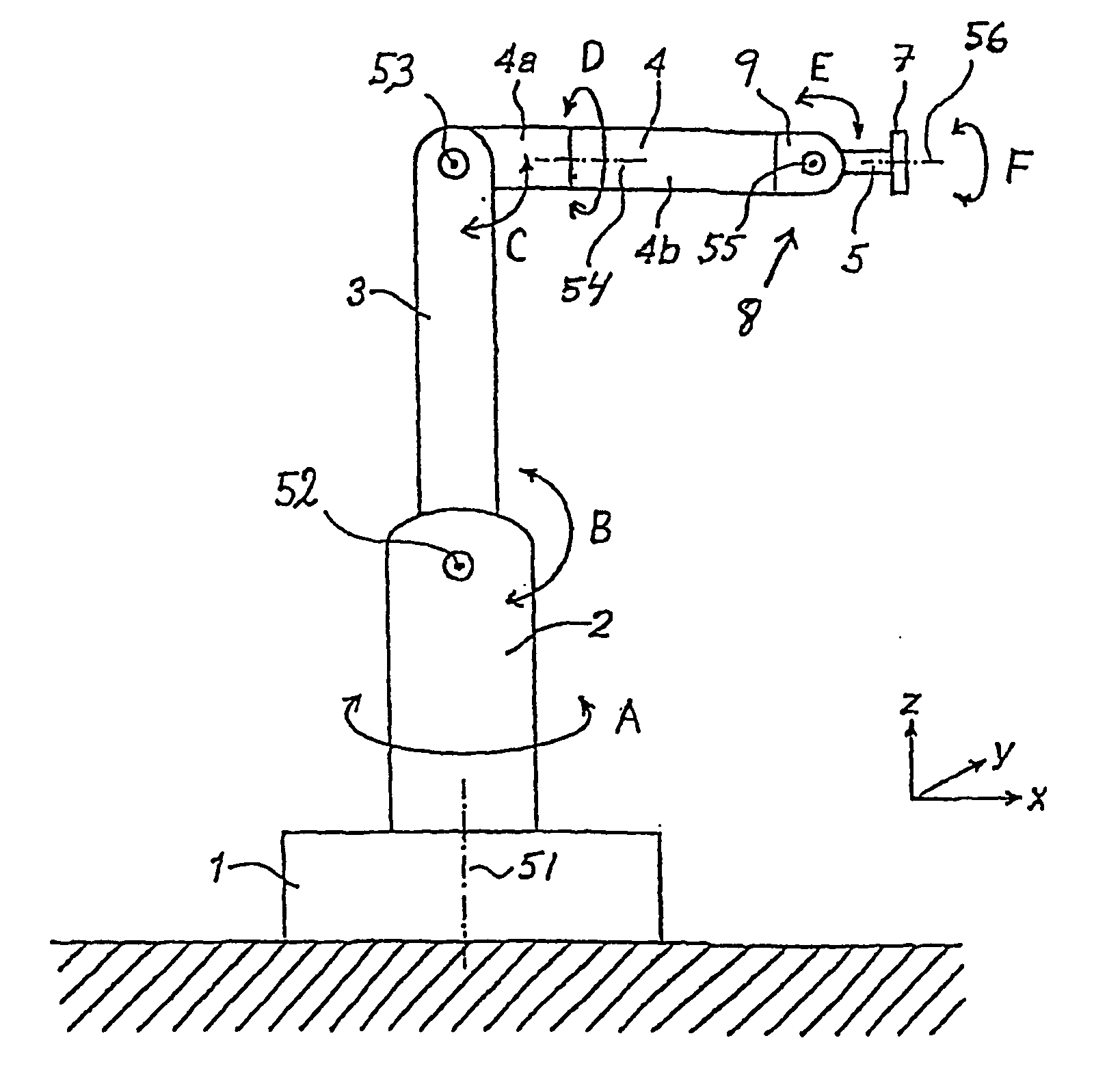
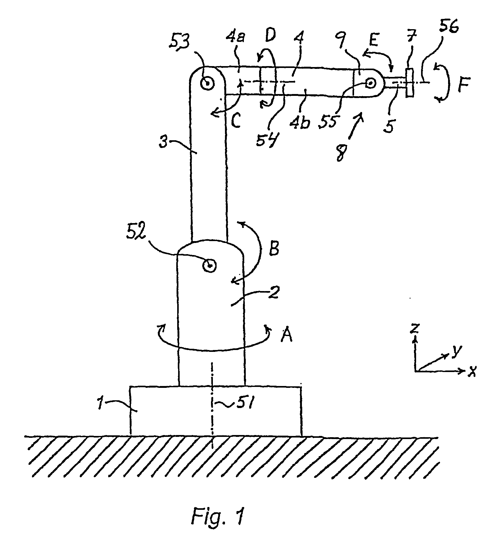
[0023]FIG. 1 shows an example of an industrial robot comprising a robot wrist 8. The robot comprises a foot 1, which is mounted against a base. The robot further comprises a stand 2, which is rotatable in relation to the foot 1 about a first axis 51. The rotary motion of the stand about this first axis 51 is indicated in FIG. 1 by the arrow A. At the end of the stand, a first robot arm 3 is rotatably journalled in relation to the stand about a second axis 52. The rotary motion of the first robot arm about this second axis 52 is indicated in FIG. 1 by the arrow B. The industrial robot shown further comprises a second robot arm 4, which is rotatably journalled at the outer end of the first robot arm about a third axis 53. The rotary motion of the second robot arm about this third axis 53 is indicated in FIG. 1 by the arrow C. The second robot arm 4 comprises two parts, one inner part 4a and one outer part 4b, the outer part 4b being rotatable in relation to the inner part 4a about a f...


PUM


Abstract

A robot wrist for an industrial robot. A wrist housing and a wrist part, designated a tilt, are journalled at the wrist housing. The tilt is rotatable relative to the wrist housing about an axis of rotation and includes a drive unit including a motor with a motor housing. A shell part of the motor housing is designed to connect the tilt to the wrist housing.

Description

TECHNICAL FIELD [0001] The present invention relates to a robot wrist for an industrial robot, said robot wrist comprising a wrist part, here referred to as a tilt, journalled at a wrist housing. The tilt is rotatable relative to the wrist housing about an axis of rotation and comprises a drive unit including a motor with a motor housing. The invention also relates to an industrial robot and a tilt for a robot wrist. BACKGROUND ART [0002] An industrial robot is composed of interconnected robot parts. Two adjacent robot parts may be interconnected so that they are either rotatable or turnable in relation to each other about an axis of rotation or are linearly displaceable in relation to each other. An industrial robot often comprises a tilt supporting a toolholder. The tilt is connected to an arm of the robot in a so-called robot wrist. The toolholder usually consists of a rotatable holder on which tool may be attached. The industrial robot is adapted to displace and rotate the robot...

Claims


Application Information

Patent Timeline
IPC IPC(8): B66F9/16B25J9/00B25J17/02
CPCB25J9/0009B25J17/0241
Inventor LUNDSTROM, CHRISTERNISSFOLK, RAFAEL
Owner ABB (SCHWEIZ) AG
Why Eureka
Try Eureka