Method for reducing degradation in a fuel cell

a fuel cell and degradation technology, applied in the field of reducing degradation in fuel cells or cells, can solve the problems of increasing the cost of fuel cell production, and many technical challenges, and achieve the effect of reducing catalyst dissolution

Inactive Publication Date: 2006-08-17
WL GORE & ASSOC INC
View PDF11 Cites 16 Cited by
  • Summary
  • Abstract
  • Description
  • Claims
  • Application Information

AI Technical Summary

Benefits of technology

[0011] The instant invention is a method of reducing catalyst dissolution in the cathode of a membrane electrode assembly fuel cell, the method comprising the steps of: (a) preparing a membrane electrode assembly comprising an anode, a cathode and a polymer electrolyte membrane interposed between the anode and the cathode; (b) assembling a fuel cell using the membrane electrode assembly; (c) applying a fluid comprising an oxidan

Problems solved by technology

As with any electrochemical device that operates using fluid reactants, unique challenges exist for achieving both high performance and long operating times. In order to achieve high performance it is necessary to reduce the electrical and ionic resistance of components within the device.
However, many technical challenges are still ahead.
However, reducing the membranes physical thickness can increase the susceptibility to damage from other device components leading to shorter cell lifetimes. Various improvements have been developed to mitigate this problem.
This decrease, described by various practitioners as voltage decay, fuel cell durability, or fuel cell stability, is not desirable because less useful work is obtained as the cell ages during use.
Ultimately, the cell or stack will eventually produce so little power that it is no longer useful at all.
The causes of this power loss wit

Method used


Image

  • Method for reducing degradation in a fuel cell
  • Method for reducing degradation in a fuel cell
  • Method for reducing degradation in a fuel cell

Examples


examples

Description of Test Methods

Membrane Electrode Assemblies

[0046] Several types of MEAs were used to evaluate the instant invention in this application. The polymer electrolyte membrane in the MEAs used herein consisted of either a GORE-SELECT® composite membrane of an ePTFE-reinforced perfluorosulfonic acid ionomer (W. L. Gore & Associates, Inc. Newark, Del.), or a non-reinforced perfluorosulfonic acid membrane, NAFION® 112 ionomer membrane (E. I. Du Pont de Nemours Company, Wilmington, Del.). Various different thicknesses of the GORE-SELECT® composite membrane were used as described more fully in the examples below. The thickness of the NAFION® membrane was 50 micrometers.

[0047] In all cases, PRIMEA® Series 5510 electrodes (W. L. Gore & Associates, Inc., Newark, Del.) with a loading of 0.4 mg / cm2 Pt were used as both the anode and cathode. These electrodes were laminated onto the membrane using standard procedures know in the art. In particular, the membrane was placed between t...

examples 1-2

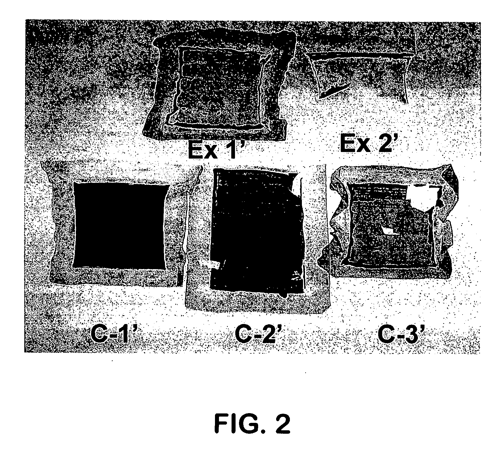
[0076] Two cells were assembled and tested to confirm the instant invention. In Example 1, a reducing agent, in this case, hydrogen, was supplied to the cell externally by adding hydrogen gas flowing at 2.5 cm3 / min hydrogen at standard conditions to the air being supplied to the cathode as the oxidant. The hydrogen was added at this flow rate through the entire test protocol. In Example 2, the reducing agent, in this case hydrogen, was supplied internally by manipulating the membrane through the use of a very thin GORE-SELECT® membrane to increase hydrogen cross-over. The cell operating conditions were identical to those used in Comparative Example C-3. The results (Table 2) indicate that in Example 1 the extent of Pt dissolution was far less than in Comparative Example C-3, which used the same operating conditions. The reduction or absence of Pt in the membrane was confirmed by visual observation (FIG. 2), x-ray fluorescence measurement (Table 2) and SEM observation. In the case of...


PUM


Abstract

The invention is a method of reducing catalyst dissolution in the cathode of a membrane electrode assembly fuel cell, said method comprising the steps of: (a) preparing a membrane electrode assembly comprising an anode, a cathode and a polymer electrolyte membrane interposed between said anode and said cathode; (b) assembling a fuel cell using said membrane electrode assembly; (c) applying a fluid comprising an oxidant to said cathode of said membrane electrode assembly; (d) applying a fluid comprising a fuel to said anode of said membrane electrode assembly; and (e) supplying a sufficient quantity of reducing agent to said cathode to maintain the average open-circuit voltage of said cathode at less than about 0.98 V.

Description

FIELD OF THE INVENTION [0001] The present invention relates to a method of reducing degradation in a fuel cell or cells to improve their durability and life and therefore their usefulness. BACKGROUND OF THE INVENTION [0002] Fuel cells are devices that convert fluid streams containing a fuel, for example hydrogen, and an oxidizing species, for example, oxygen or air, to electricity, heat and reaction products. Such devices comprise an anode, where the fuel is provided; a cathode, where the oxidizing species is provided; and an electrolyte separating the two. The fuel and / or oxidant typically are a liquid or gaseous material. The electrolyte is an electronic insulator that separates the fuel and oxidant. It provides an ionic pathway for the ions to move between the anode where the ions are produced by reaction of the fuel, to the cathode, where they are used to produce the product. The electrons produced during formation of the ions are used in an external circuit, thus producing elec...

Claims


Application Information

Patent Timeline
IPC IPC(8): H01M8/00H01M8/10
CPCH01M8/008H01M8/04223H01M8/1023H01M8/1039Y10T156/1116H01M8/1086Y02E60/522Y10T156/11H01M8/1067Y02P70/50Y02W30/84Y02E60/50H01M8/0263H01M8/026H01M8/02H01M4/88H01M4/86H01M8/0273
Inventor LIU, WENJOHNSON, WILLIAM B.CLEGHORN, SIMON J.C.REID, RONALD M.
Owner WL GORE & ASSOC INC
Why Eureka
Try Eureka