
Sealing end for a heat conductor and method of constructing same

a heat conductor and sealing end technology, applied in the field of heat conductors, can solve the problems of inability to meet the demanding requirements of higher availability, vulnerable cracks in vacuum states, etc., and achieve the effect of saving manufacturing costs and being convenient and efficien

Inactive Publication Date: 2006-08-17
FORCECON TECH CO LTD
View PDF2 Cites 5 Cited by
  • Summary
  • Abstract
  • Description
  • Claims
  • Application Information

AI Technical Summary

Benefits of technology

"The present invention is a vacuum pump with a heat conductor that is designed to be sealed without needing to compress it, which saves money and makes it stronger and more durable. This is possible because the sealing end of the heat conductor is only designed to be welded close, which prevents any deformation from compression."

Problems solved by technology

However, the sealing method and construction for typical heat pipe will yield the following problems in practical applications: 1.
Owing to excessive amount of deformation at the compressed part of heat pipe, fatigue of materials will likely lead to vulnerable crack against a vacuum state at the moment of compression or in the future.
The overall sealing behavior of heat pipe must cover a time-consuming compression and welding process, which cannot meet the demanding requirement of higher availability.

Method used


Image

  • Sealing end for a heat conductor and method of constructing same
  • Sealing end for a heat conductor and method of constructing same
  • Sealing end for a heat conductor and method of constructing same

Examples


Embodiment Construction

[0018] The features and the advantages of the present invention will be more readily understood upon a thoughtful deliberation of the following detailed description of a preferred embodiment of the present invention with reference to the accompanying drawings.

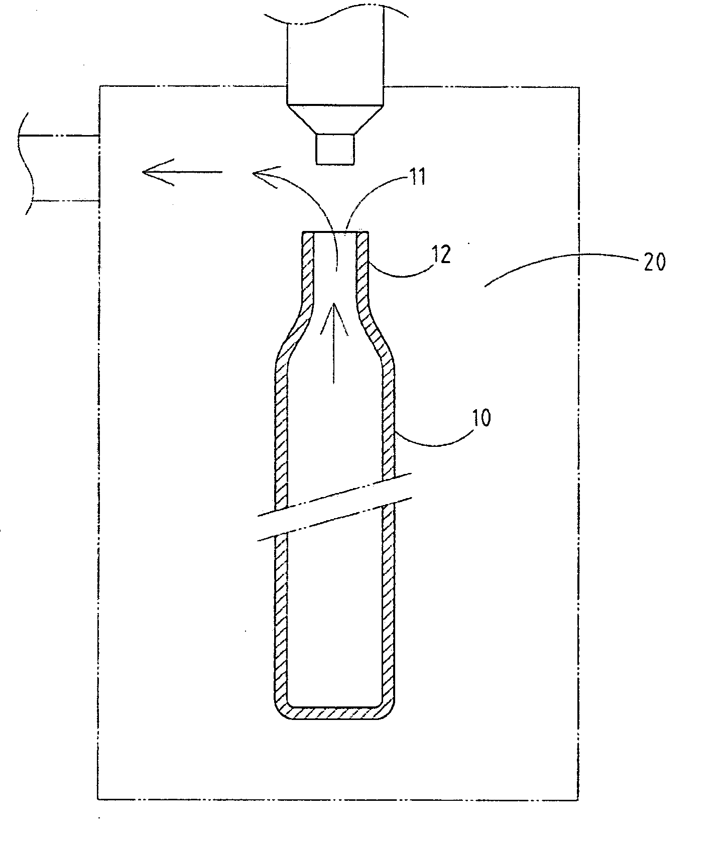
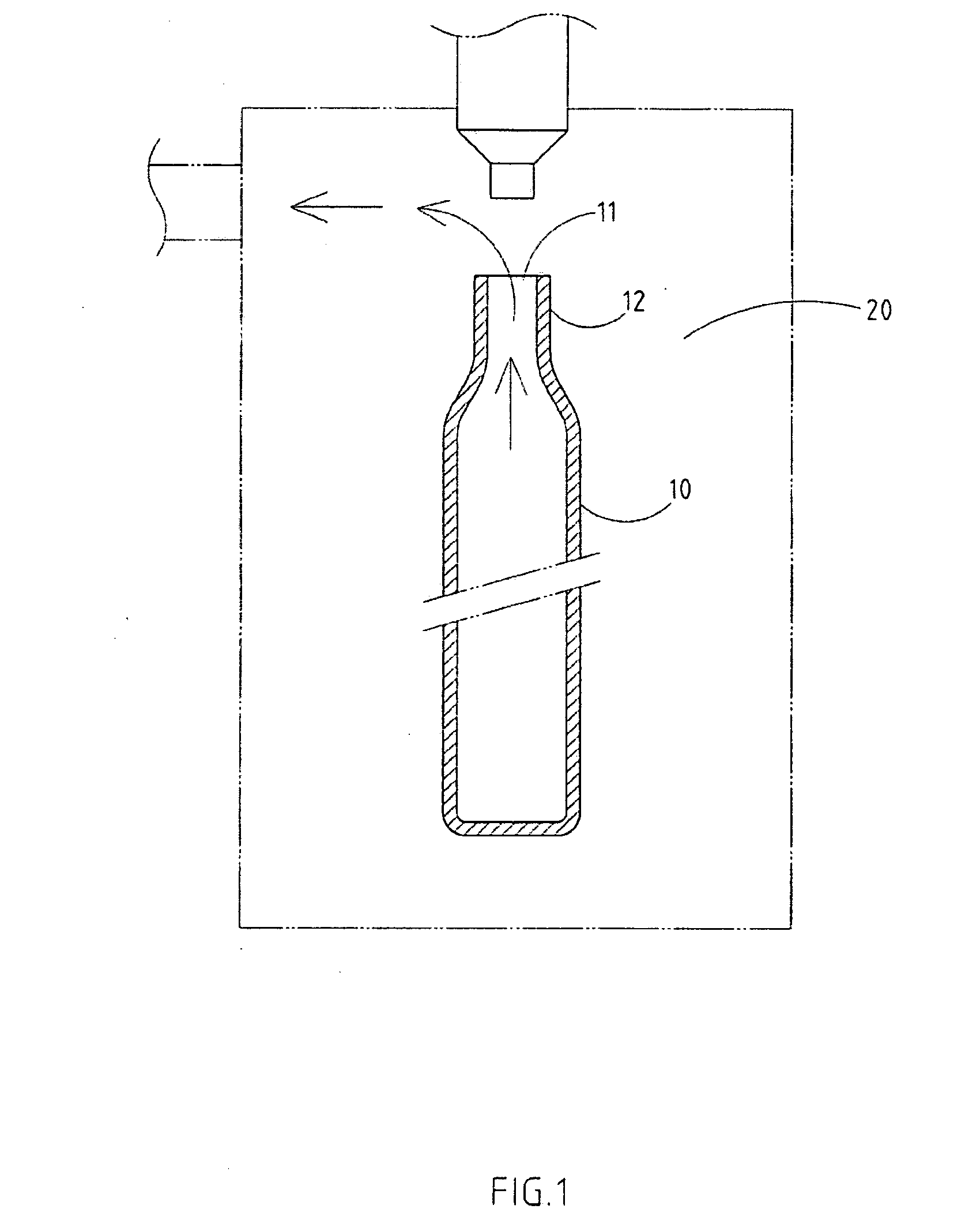
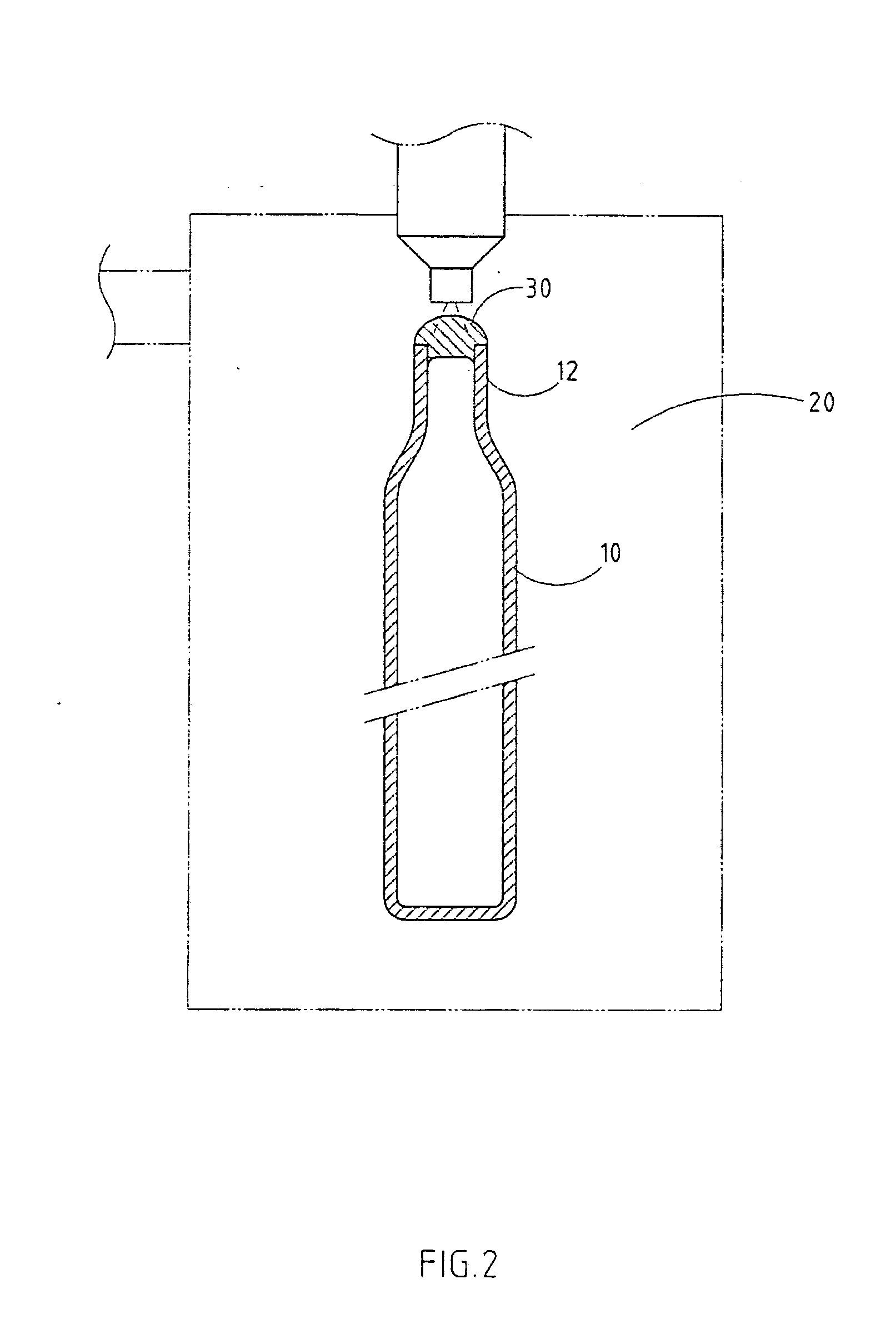
[0019] As shown in FIGS. 1-4, the sealing method and construction of sealing end for a heat conductor embodied in the present invention, in which the heat conductor is a heat pipe 10; the features of its sealing method are: [0020] a. A preset enclosed operating space 20, wherein a heat pipe 10 for vacuum pumping and sealing is wholly or partially placed and an open end 11 is preset for the heat pipe 10; [0021] b. As shown in FIG. 1, vacuum pumping is performed for entire enclosed operating space 20, thereby finishing the vacuum pumping procedure of the heat pipe 10; and [0022] c. As shown in FIG. 2, the open end 11 of a heat pipe 10 is welded by fusing within enclosed operating space 20, wherein a welded close end 30 is formed...


PUM

PropertyMeasurementUnit
heat conductionaaaaaaaaaa
vacuum constantaaaaaaaaaa
structural strengthaaaaaaaaaa

Abstract

The sealing method and construction of the sealing end for a heat conductor includes a heat conductor for vacuum pumping and sealing placed within an enclosed operating space, wherein an open end is preset for the heat conductor. Next, vacuum pumping is performed for entire enclosed operating space, thereby finishing the vacuum pumping procedure of heat pipe. Then, the open end of heat pipe is welded by fusing within enclosed operating space, wherein the sealing end of heat conductor forms a welded close end. A compression procedure can be neglected, thereby saving more manufacturing cost and offering a higher structural strength for the sealing part.

Description

RELATED U.S. APPLICATIONS [0001] Not applicable. STATEMENT REGARDING FEDERALLY SPONSORED RESEARCH OR DEVELOPMENT [0002] Not applicable. REFERENCE TO MICROFICHE APPENDIX. [0003] Not applicable. FIELD OF THE INVENTION [0004] The present invention relates generally to a heat conductor, and more particularly to a heat conductor that is exclusively intended for overall or partial vacuum pumping in an enclosed environment via a sealing method or sealing by fusing without compression joint. BACKGROUND OF THE INVENTION [0005] To ensure a better heat conduction effect, a heat conductor is generally fitted with an opening at one side for vacuum pumping. After that, it is required to keep the vacuum constant by sealing this preset opening. The present invention is intended to improve the sealing method and construction of sealing end of heat conductor. As shown in FIGS. 7-8 for the sealing method of typical heat conductor's sealing end, the heat conductor (i.e. a heat pipe 40) is firstly pumpe...

Claims


Application Information

Patent Timeline
Patent Type & Authority Applications(United States)
IPC IPC(8): H01R13/40
CPCB23K31/02B23K2201/12B23K2101/12
Inventor SHIH, MING-CYUANHE, SIN-WEICHANG, JHONG-YAN
Owner FORCECON TECH CO LTD
Learn More