Transceiver front-end

a transceiver and front-end technology, applied in the direction of transmission, electrical equipment, etc., can solve the problems of added noise, unfavorable inconvenient use of buffer amplifiers, so as to achieve low distortion and noise

Active Publication Date: 2006-08-17
AVAGO TECH INT SALES PTE LTD
View PDF30 Cites 30 Cited by
  • Summary
  • Abstract
  • Description
  • Claims
  • Application Information

AI Technical Summary

Benefits of technology

[0012] The present invention is a transceiver front-end having a hybrid circuit, a high-pass filter, and a gain stage, that permits the reduction or the complete elimination of buffer amplifiers. Buffer amplifiers can be eliminated because the hybrid circuit and / or the high-pass filter are adapted so that they can be directly connected to each other, without a loss in performance. Furthermore, the high-pass filter and / or the gain stage are also adapted so they can be directly connected.
[0016] The elimination of buffer amplifiers enables completely passive signal processing from an input to the transceiver front-end to the first stage of the receiver, using nearly zero power. Furthermore, a passive transceiver front-end eliminates the need for an external power source, and therefore does not generate excess heat that would need to be removed by a heat sink or fan. Still further, passive signal processing adds less distortion and noise to the receive signal than active signal processing.

Problems solved by technology

A conventional transceiver front-end has some known limitations.
Each buffer amplifier consumes power and generates unwanted heat that should be removed from the substrate.
Furthermore, buffer amplifiers are active devices that generate added noise that can degrade overall system noise figure.
At the front-end, the added noise is especially detrimental to the overall system noise figure.
The dynamic range requirement can complicate the buffer amplifier design and the design of the transceiver front-end.

Method used


Image

  • Transceiver front-end
  • Transceiver front-end
  • Transceiver front-end

Examples


Embodiment Construction

1. Example Transceiver Application

[0029] Before describing the invention in detail, it is useful to describe an example communications environment for the invention. The front-end invention is not limited to the communications environment that is described herein, as the transceiver front-end circuitry is applicable to other communications and non-communications applications as will be understood to those skilled in the relevant arts based on the discussions given herein.

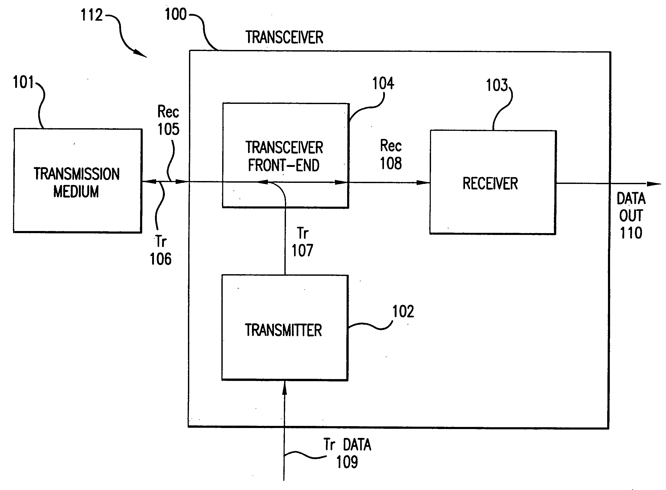
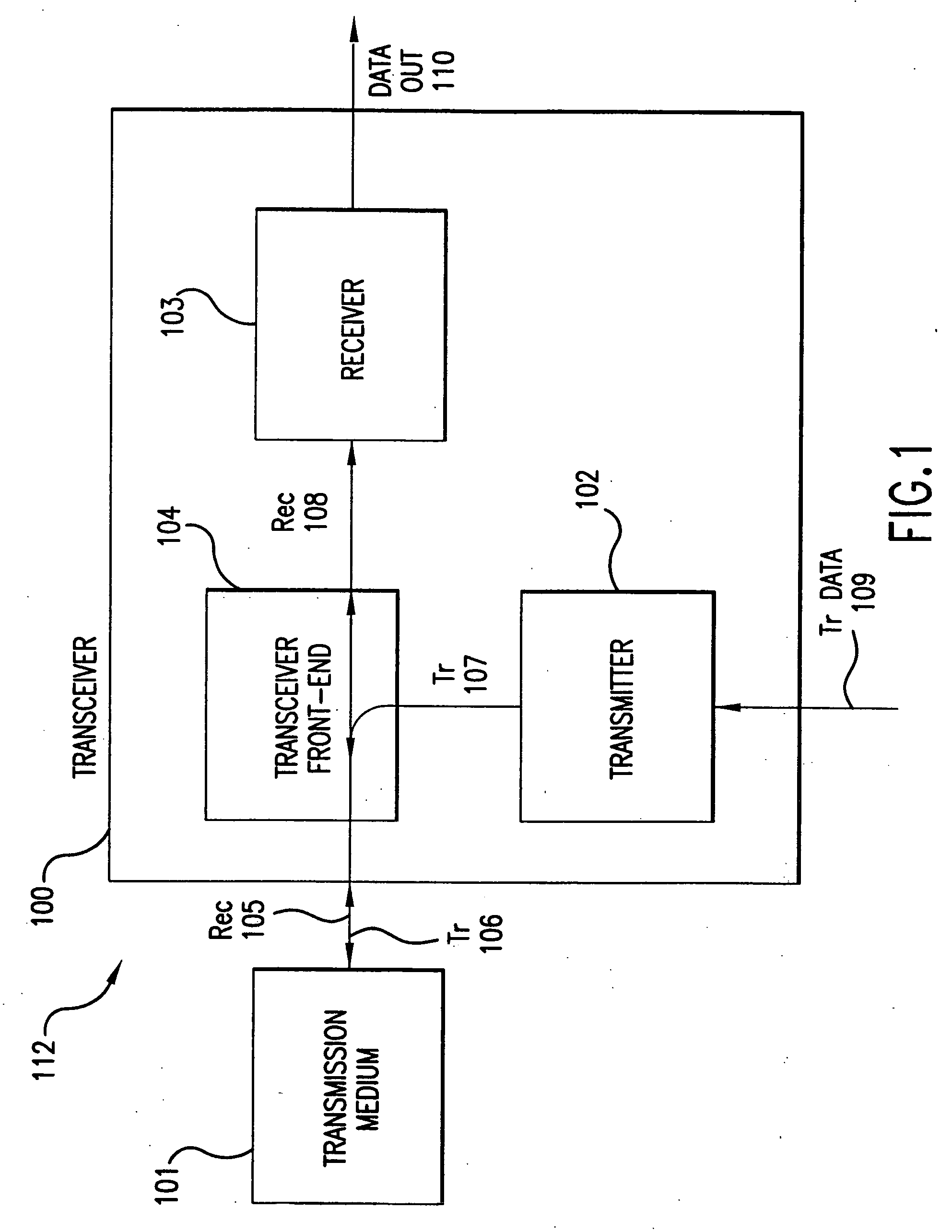
[0030]FIG. 1 illustrates a communications environment 112 having a transmission medium 101 and a transceiver 100. The transceiver 100 includes at least a transmitter 102, a receiver 103, and a transceiver front-end 104. The transmission medium 101 transfers communications signals (e.g. voice and / or data) to and from the transceiver 100. Exemplary types of the transmission media 101 include a cable, an optical fiber, public airways, or any other medium capable of carrying communications signals. The operation of t...


PUM


Abstract

A transceiver front-end provides an interface between a transmission medium and transmitter, and between a transmission medium and receiver. The transceiver front-end includes a hybrid circuit, a high-pass filter, and a gain stage, that permits the reduction or the complete elimination of buffer amplifiers. Buffer amplifiers can be eliminated because the hybrid circuit and / or the high-pass filter are adapted so that they can be directly connected to each other, without a loss in circuit performance. Furthermore, the high-pass filter and / or the gain stage are also adapted so they can be directly connected. As such, the transceiver front-end can be constructed using all passive components, reducing or eliminating excess heat generation.

Description

BACKGROUND OF THE INVENTION [0001] 1. Field of the Invention [0002] The present invention is generally related to a front-end circuit for a transceiver, and more specifically to a low-power transceiver front-end that can be implemented on a single substrate without the need for buffer amplifiers. [0003] 2. Background Art [0004] Electronic communication systems include transmitter and receiver circuits. In many communication systems, transmitters and receivers are present in every node of the system and are often combined to form what is called a transceiver. [0005] A transceiver front-end is a circuit that interfaces a transmission medium with both the receiver and transmitter of a transceiver. Exemplary transmission mediums include a cable, optical fiber, antenna, etc. [0006] There are typically two input signals to the transceiver front-end, a receive signal and a transmit signal. The receive input signal comes from the transmission medium and is intended for the receiver portion ...

Claims


Application Information

Patent Timeline
Patent Type & Authority Applications(United States)
IPC IPC(8): H04B1/44H04B1/58
CPCH04B1/583
Inventor WESTRA, JAN ROELOFVAN DE PLASSCHE, RUDY J.LIN, CHI-HUNG
Owner AVAGO TECH INT SALES PTE LTD
Why Eureka
Try Eureka