

Tubular roller, method of manufacturing the same, and electro-photographic image forming apparatus having the same
a technology of electro-photographic imaging and tubular rollers, which is applied in the direction of manufacturing tools, portable power-driven tools, instruments, etc., can solve the problems of increasing toner stress, reducing the life of the developing process, and bad images, so as to reduce the migration of low molecular weight additives, low cost, and low hardness
- Summary
- Abstract
- Description
- Claims
- Application Information
AI Technical Summary
Benefits of technology
Problems solved by technology
Method used
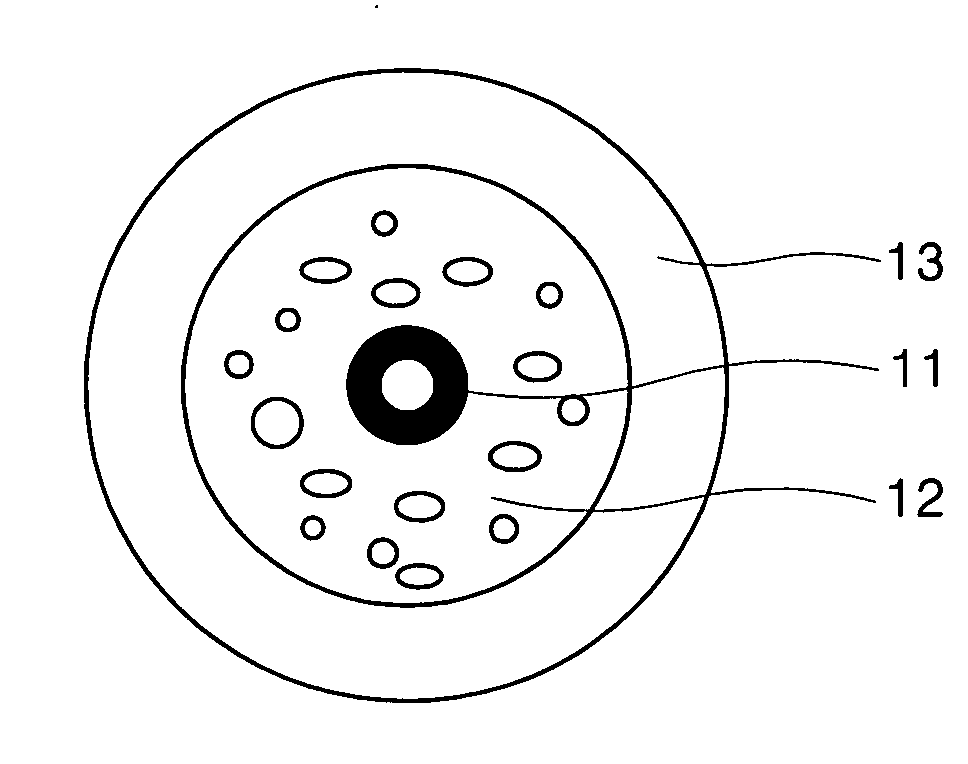
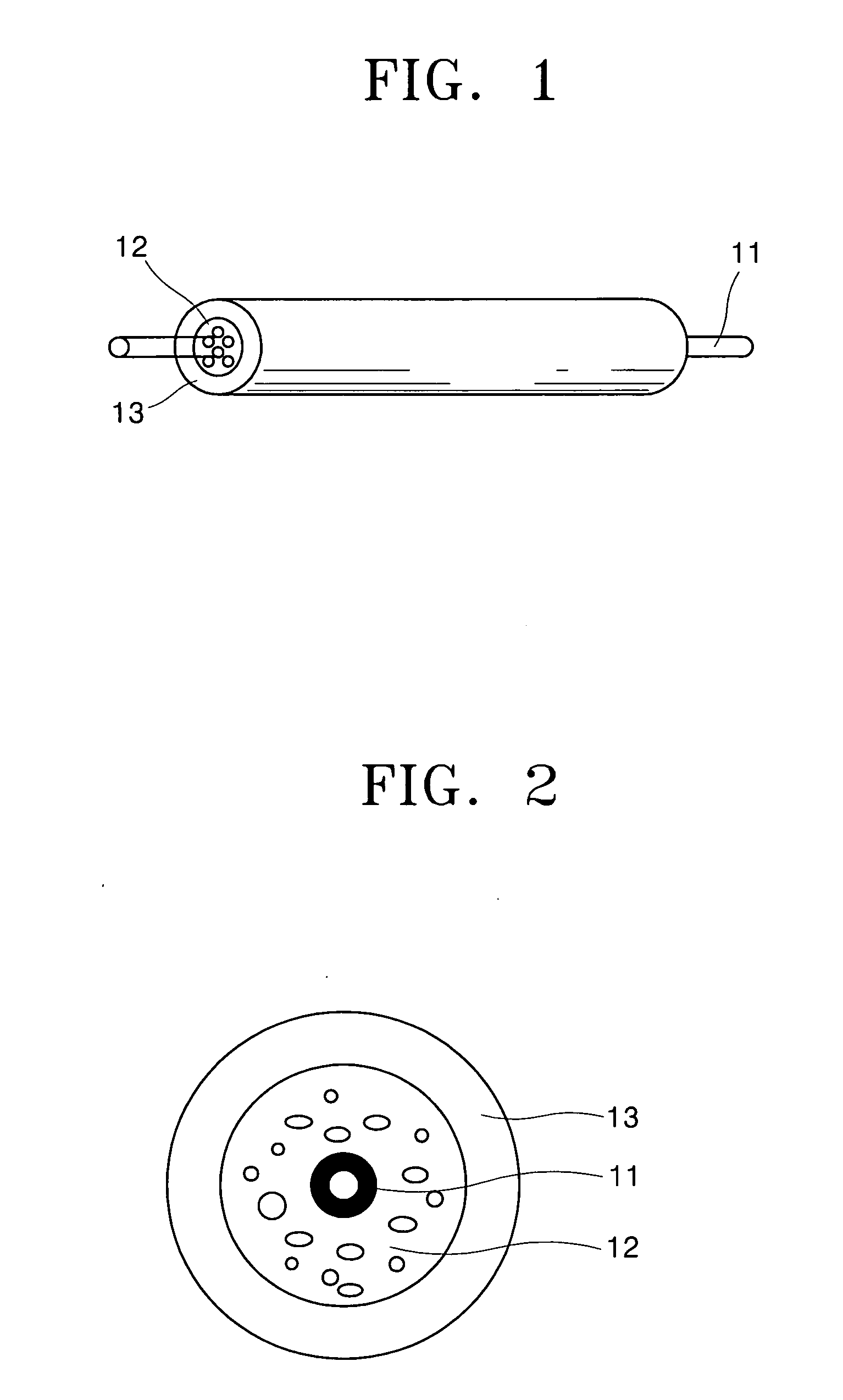
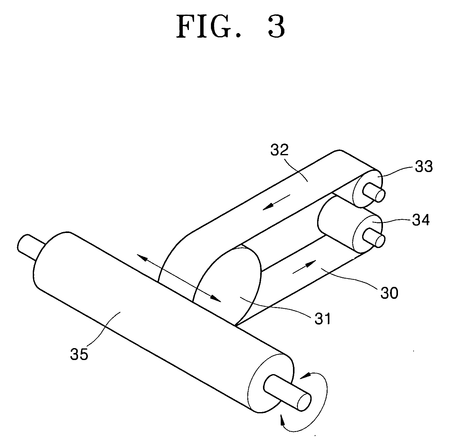
Image

Examples
example 1
Manufacture of Ionic Conductive Tubular Roller
[0066] To manufacture an outer tubular layer, 10 parts by weight of NBR, 90 parts by weight of ECO, 8 parts by weight of an ammonium salt of a perfluorinated alkyl acid, 5 parts by weight of sulfur, and 1 part by weight of divinyl benzene were mixed at atmospheric pressure and room temperature. Then, the mixture was injected into a hopper of an extruder, and extruded at a temperature of 50-100° C. and an extrusion speed of 30-100 rpm. The extruded mixture (rubber) was passed through a mold having a double-pipe round shape to obtain a tubular shape. Here, the extruded material was not yet sulfurated. The mold was manufactured using a die having a diameter φ of 13-15, so that the final mold had a diameter φ of 13-15.
[0067] Since heat was generated during the mixing process, the mixing process was performed at a lower temperature than a half period temperature (e.g. 80-150° C.) of a foaming agent ACA.
[0068] To provide an inner foam layer...
example 2
Electronic Conductive Tubular Roller
[0070] An electronic conductive tubular roller was manufactured in the same manner as for the ionic conductive tubular roller in Example 1, except that carbon black was used as a conductive additive instead of 90 parts by weight of ECO and 8 parts by weight of an ammonium salt of a perfluorinated alkyl acid.
[0071] 100 parts by weight of styrene-butadiene rubber, 20 parts by weight of carbon black, 5 parts by weigh of sulfur, 1 part by weight of divinyl benzene, and 3 parts by weight of ACA were mixed at an atmospheric pressure and room temperature.
[0072] The outer tubular layer and the inner foam layer were manufactured by the same method as described in Example 1. The electronic conductive extrusion material was injected into the outer tubular layer, and then heated in an oven to allow sulfuration and a foaming reaction. The temperature of the oven for the forming reaction was maintained within the range of 130-180° C.
[0073] The surface rough...
PUM
| Property | Measurement | Unit |
|---|---|---|
| electrical resistance | aaaaa | aaaaa |
| electrical resistance | aaaaa | aaaaa |
| electrical resistance | aaaaa | aaaaa |
Abstract
Description
Claims
Application Information