Method for erecting a stay

a technology of erecting a stay and a beam, which is applied in the direction of cable stayed bridges, bridges, building repairs, etc., can solve the problems of not being able to be hauled up into position, and the towers are overengineered in a way that is not easily movable, so as to prevent friction from damaging the beams

Active Publication Date: 2006-08-24
FREYSSINET INT STUP
View PDF4 Cites 14 Cited by
  • Summary
  • Abstract
  • Description
  • Claims
  • Application Information

AI Technical Summary

Benefits of technology

[0021] The shuttle may include, in at least some of the iterations of steps [a] to [c], means for parting the reinforcements of the further group from the compacted reinforcements, it being possible for these means to comprise at least one roller mounted to pivot about an axis substantially perpendicular to the first and second lines. This roller presses against the compacted reinforcements as the shuttle and the reinforcements of the further group are hauled through when the space available becomes smaller, to prevent friction from damaging the reinforcements. A roller may in particular be mounted at the front of the shuttle relative to a direction of travel of the shuttle through the casing during step [b].

Problems solved by technology

Furthermore, on stayed constructions with a very long span (in excess of 500 meters), the drag load on the sheaf of stays is dominant over the action of the wind on the deck and may lead to appreciable over-engineering of the towers.
This is because the stays used in large bridges are very heavy, which means that it is not conceivable for them to be hauled up into position having prefabricated them on the deck or at a prefabrication area.

Method used


Image

  • Method for erecting a stay
  • Method for erecting a stay
  • Method for erecting a stay

Examples


Embodiment Construction

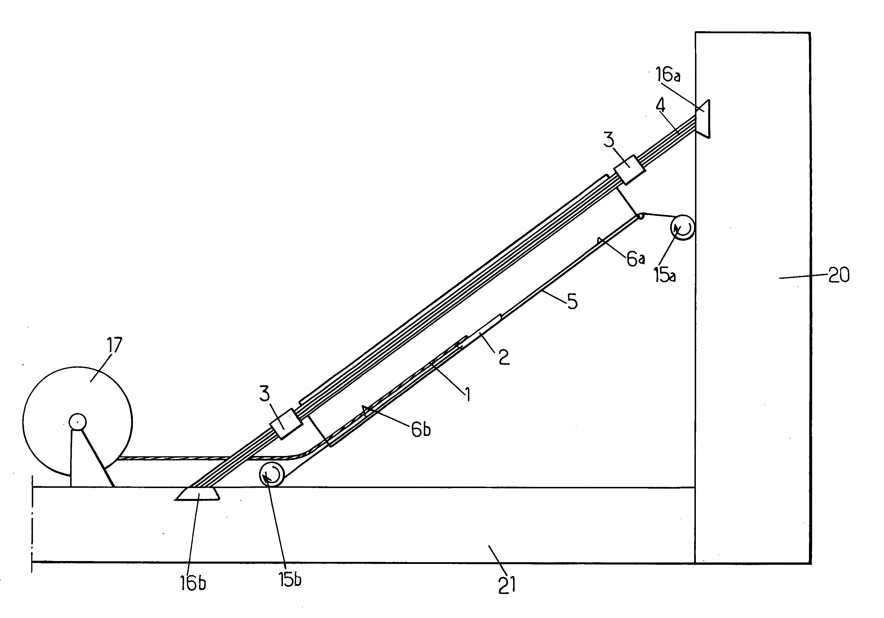
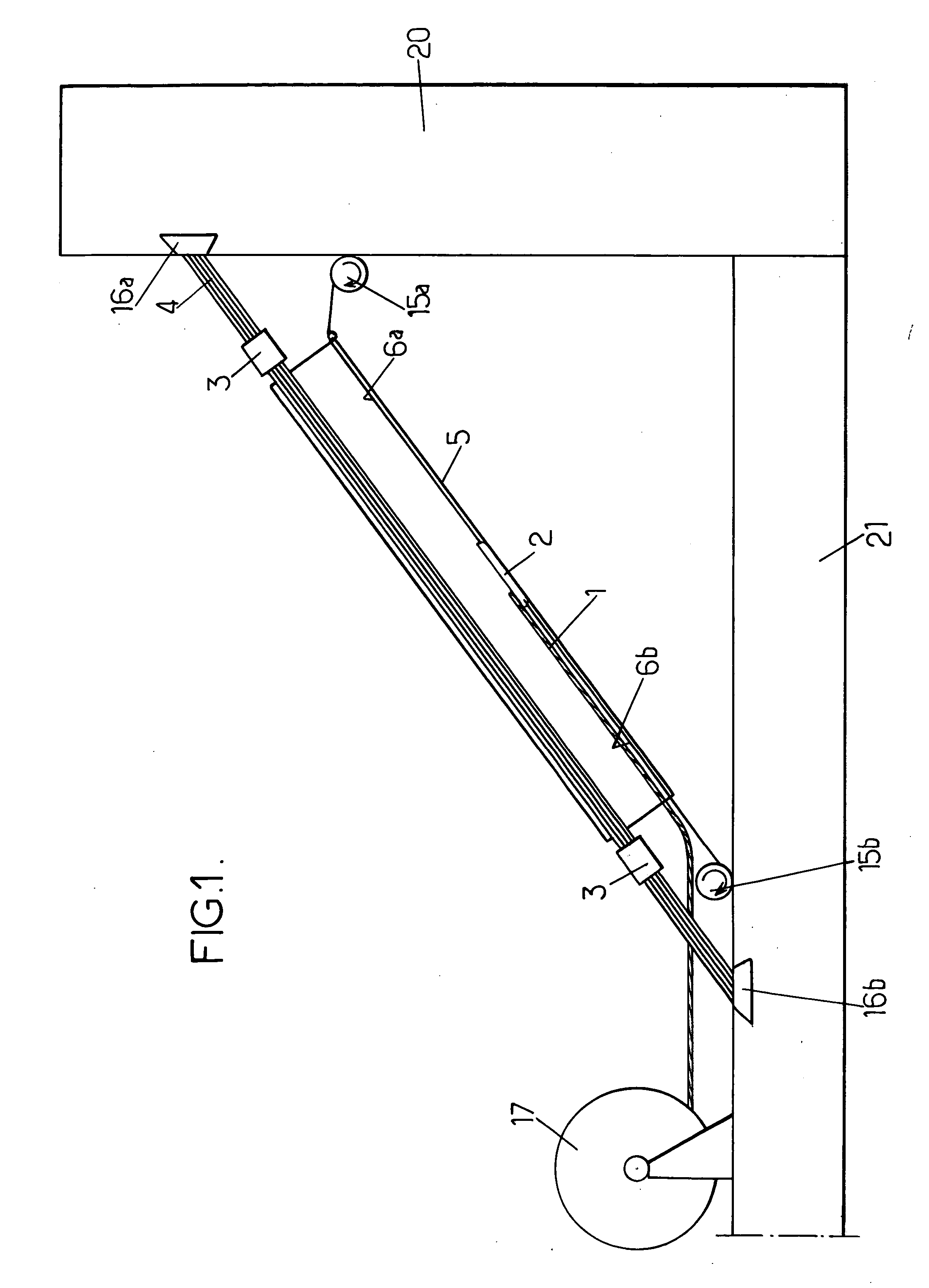
[0032] The invention finds an application in particular in the field of stayed bridges. Here we consider a stay contained in a casing 5 and stretching between a tower 20 and the deck 21 (FIG. 1). The stay in question may be very long, for example, in excess of a 100 meters long. It may contain a potentially high number of elementary reinforcements, of the order of one hundred or more.

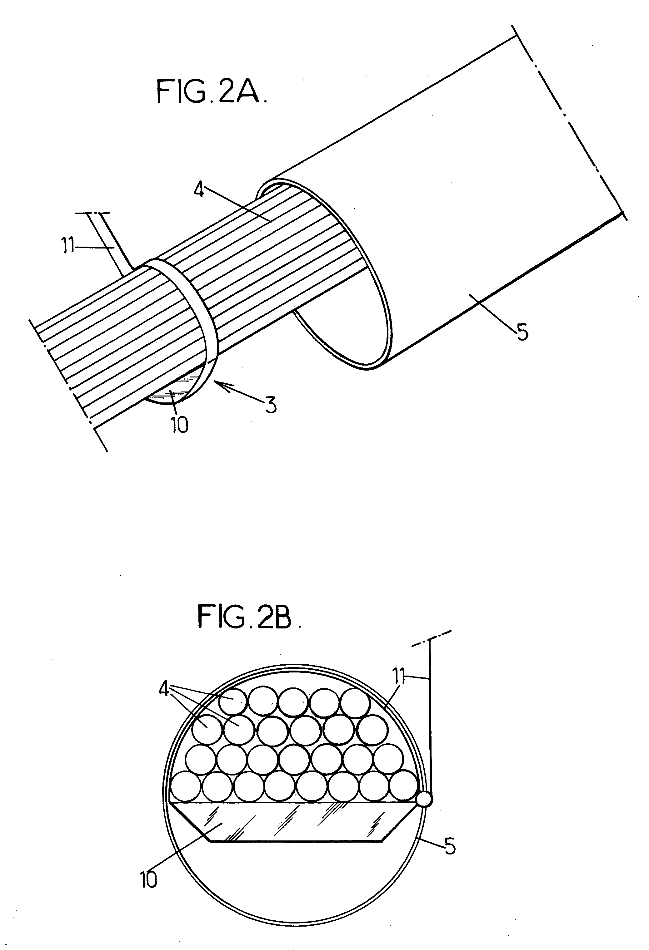
[0033] The reinforcements of the stay consist in strand parts 4 grouped together into a bundle housed within the casing 5. Each strand part is tensioned and anchored at its two ends in two anchoring regions 16a, 16b one situated on the tower 20 and the other on the deck 21, respectively. The anchoring means placed in the regions 16a, 16b may be of conventional type with, for example, an anchor block bearing against the structure and equipped with frustoconical orifices to accommodate frustoconical jaws wedged about each strand part.

[0034] In a first step of the method for erecting the stay, the casing...


PUM


Abstract

A stay comprises an inclined casing and a bundle of substantially parallel taut reinforcements lodged in the casing and individually anchored in a first and a second anchoring region. According to the invention, the casing and some of the reinforcements are installed by applying substantially uniform tension values to the reinforcements, then several iterations of the following steps are formed: compacting the installed reinforcements, at least at one end of the casing; slipping a further group of reinforcements along inside the casing, in a space left available by the compacted reinforcements; and tensioning each reinforcement of the further group between the first and second anchoring regions so that all the installed reinforcements exhibit substantially uniform tension values.

Description

CROSS REFERENCE TO RELATED APPLICATIONS [0001] This application claims priority to France Patent Application Ser. No. FR 02 16090, filed Dec. 18, 2002, which is incorporated herein by reference in its entirety. BACKGROUND OF THE INVENTION [0002] The present invention relates to the installation of taut reinforcements such as strand parts inside a casing to produce a stay belonging to the suspension system for a civil engineering construction. [0003] In a stayed suspension, one or more towers support a structure, such as the deck of a bridge for example, via a collection of stays following oblique paths between a tower and the structure. A stay is a cable made up of a collection of reinforcements stretched between two end anchor points and generally surrounded by a casing. These reinforcements are often metal strand parts. In the case of a stayed bridge, each reinforcement is anchored to a tower and to the deck of the bridge that it plays a part in supporting. [0004] European Patent ...

Claims


Application Information

Patent Timeline
Patent Type & Authority Applications(United States)
IPC IPC(8): E04B1/00E01D11/04E01D19/16E01D21/00E04H12/20
CPCE01D19/16E01D11/04
Inventor LECINQ, BENOITMESSEIN, JEAN-PIERREPERCHERON, JEAN-CLAUDEROBERTSON, CRAIG
Owner FREYSSINET INT STUP
Why Eureka
Try Eureka