Removing carbon dioxide from waste streams through co-generation of carbonate and/or bicarbonate minerals

a technology of carbon dioxide and waste stream, which is applied in the field of removing carbon dioxide, can solve the problems of large cost of sequestering techniques, less improvement to be extracted from this field of endeavor, and generally not economically feasible techniques, so as to improve the ecologic efficiency of the process, improve the electrical return, and improve the effect of environmental efficiencies

Active Publication Date: 2006-08-24
CARBONFREE CHEM HLDG LLC
View PDF15 Cites 163 Cited by
  • Summary
  • Abstract
  • Description
  • Claims
  • Application Information

AI Technical Summary

Benefits of technology

[0070] Like any other method or apparatus that performs work to accomplish an objective, many embodiments of the present invention consume some energy to accomplish the absorption of CO2 and other chemicals from flue-gas streams and to accomplish the other objectives of embodiments of the present invention as described herein. However, one advantage of certain embodiments of the present invention is that they provide ecologic efficiencies that are superior to those of the prior art, as explained in detail in Examples 5 and 6. As is evident from the data in Examples 5 and 6, amplified waste-heat-recovery or non-greenhouse-gas-generated energy for powering the process, use of even-lower-voltage electrolysis, and improving electrical return from hydrogen-energy-recovery can further improve the ecologic efficiency of the process, up to and surpassing the point where the process is fully powered by waste-heat recovery (and the recovery of hydrogen-energy), and absorbs virtually 100% of power-plant emitted CO2.
[0071] Additionally, one benefit of employing the extreme chemistry of certain embodiments of the present invention such that they absorb the weak-acid CO2 is that the process virtually completely absorbs the strong acids, SOX and NOX, and, to a lesser extent, mercury. Tests using SOX/Ar and NOX/Ar in charged-load single-stage decarbonators have demonstrated 99%+ removal of these components of flue-gas (by “99%+,” it is meant that the presence of either pollutant in a 14 L/min flue-gas processing case was not detectable in the product air-stream by gas-chromatograph technique, i.e., they were effectively removed). In certain embodiments of the present invention, the incidental scrubbing of NOX, SOX, and mercury compounds can assume greater economic importance; i.e., by employing embodiments of the present invention, coals that contain large amounts of these compounds can be combusted in the power plant with, in some embodiments, less resulting pollution than with higher-grade coals processed without the benefit of the CO2/absorption process of certain embodiments of the present invention.
[0072] Further, the scale-ability of certain embodiments of the present invention can be carried out to extreme gradations; i.e., since, in certain embodiments, the process is electrically controlled, that electrical power expense can be virtually scaled to the individual molecule of absorbent produced at any given time. Also, the ability to accurately determine the amount of CO2 absorbed is practical and easy: weigh the carbonate/bicarbonate products formed, measure their ion ratio by assay, perform a calculation to determine moles of CO2 absorbed, and the CO2 absorbed is easily confirmed and measured (a factor that may benefit certain incentive regimes for the removal of CO2 and other chemicals in flue-gas).
[0073] Another additional benefit of certain embodiments of the present invention that distinguishes them from other CO2-removal processes is that in some market conditions, the products are worth considerably more than the reactants required or the net-power or plant-depreciation costs. In other words, certain embodiments are industrial methods of producing chlor-hydro-carbonate products at a profit, while accomplishing considerable removal of CO2 and incidental pol

Problems solved by technology

While strides in this area have improved combustion efficiency, there is little more improvement to be extracted from this field of endeavor.
Each of these sequestering techniques involves large costs in preparing CO2 for transport, accomplishing the transport, and performing the injection into a “carbon bank.” As such, these techniques are generally not economically feasible and in many cases consume more energy than the original carbon produced.
However, each of these technologies suffer due to the capital plant costs raised to

Method used


Image

  • Removing carbon dioxide from waste streams through co-generation of carbonate and/or bicarbonate minerals
  • Removing carbon dioxide from waste streams through co-generation of carbonate and/or bicarbonate minerals
  • Removing carbon dioxide from waste streams through co-generation of carbonate and/or bicarbonate minerals

Examples


example 1

CO2NaOH Bubble Column Reactor Design by Graphical Methods

[0157] In the bubble-column reactor designed for this example, there are four primary flow streams, namely: [0158] (1) Liquid flowing into the fluid of the bubble column at a given volumetric flow-rate (Vl=cubic volume of fluid per time); in the chosen case, the incoming volumetric flow-rate equals the outgoing volumetric flow rate. Hence, both are Vl). In this example, Vl=0.001 m3 / sec. [0159] (2) Vg0=the incoming volumetric flow rate of gas, which will be partially or wholly absorbed by the absorbent fluid. In this example, Vg0=0.05 m3 / sec. [0160] (3) Vg=the exiting volumetric flow-rate of gas. In this example, Vg=0.02 m3 / sec.

[0161] A bubble-column reactor was designed as bound by the above conditions. Sixty-percent incoming CO2 in a flue-gas was to be removed by bubbling through a solution of concentrated sodium hydroxide. The reaction is mass-transfer limited. The objective of the example was to calculate the reactor size...

example 2

CO2 / NaOH Bubble-Column Design by Mass-Transfer Coefficient Solution

[0167] The objective of this example was to determine the mass-transfer coefficient, kla (moles / sec / volume), from theoretical build-up. It was determined from this example that this correlative method can potentially lead to inconclusive results; i.e., this example highlights the difficulty in predicting actual results from theory due to the indeterminacy of measuring some of the critical parameters. Therefore, only experimental scaling can conclusively determine the result of a large decarbonation unit.

[0168] The following equations for gas-hold-up (εg) and mole-transfer (kLa) are from correlations from Akita and Yoshida (1973), and are valid for carbon dioxide and water systems at relatively large column heights and diameters (i.e., >0.1 m):

Gas-Hold-Up ɛ⁢ ⁢g(1-ɛ⁢ ⁢g)⁢4=C*[g*Dc⁢ ⁢2*ρ⁢ ⁢L / σ]⁢1 / 8*[g*Dc⁢ ⁢2 / vl⁢ ⁢2]⁢1 / 12*[μ⁢ ⁢g / g*Dc]

and

Mass-Transfer Coefficient

kLa(1 / sec)=[Cco2*Dco2−h20 / Dc2]*[νL / Dco2−h20]0.2*[g*...

example 3

CO2NaOH Bubble-Column Design (Depth) from Experimental Data

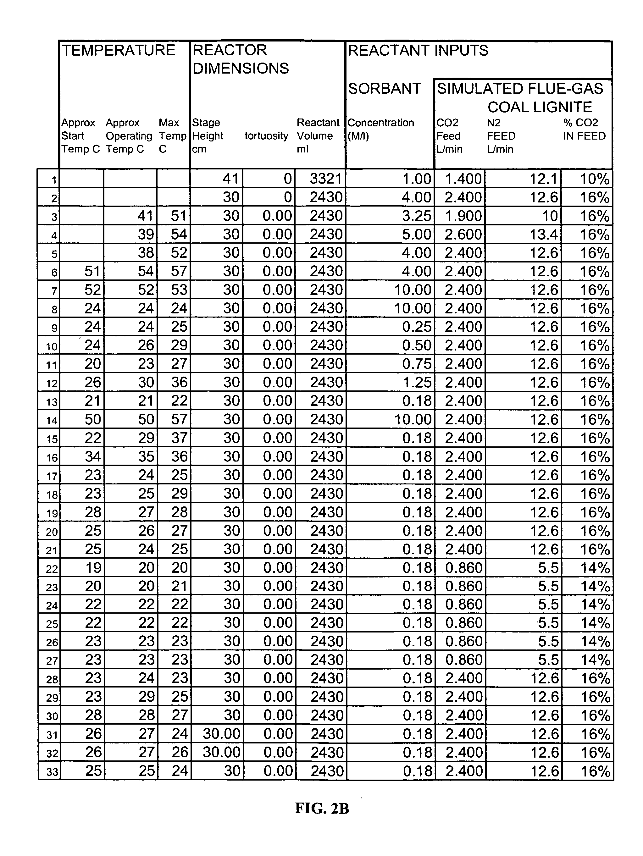
[0188] Note that the reliance of certain embodiments of the present invention upon the “short stage efficiency theory” described herein (3 m or less gas-liquid contact distance, or fluid stage height, to achieve >90% absorption) is confirmed by two different calculation techniques that are consistent with practiced chemical engineering design. However, in certain cases (as noted above) certain simplifying assumptions have been made in these design calculations, so experimental verification was indicated and performed with the Results displayed in FIGS. 2B and 2C (explained in further detail below).

[0189] Each of these processing runs obtained a certain CO2 absorption over a certain gas-liquid contact distance (namely the height of the fluid in unpacked, open bubble-column cases); e.g., 20% absorption through 30 cm of fluid.

[0190] If the gas were then passed through a second column of the same design and state-of-condition...


PUM

PropertyMeasurementUnit
Volumeaaaaaaaaaa
Volumeaaaaaaaaaa
Volumeaaaaaaaaaa

Abstract

Apparatuses and methods for removing carbon dioxide and other pollutants from a gas stream are provided. The methods include obtaining hydroxide in an aqueous mixture, and mixing the hydroxide with the gas stream to produce carbonate and/or bicarbonate. Some of the apparatuses of the present invention comprise an electrolysis chamber for providing hydroxide and mixing equipment for mixing the hydroxide with a gas stream including carbon dioxide to form an admixture including carbonate and/or bicarbonate.

Description

CROSS-REFERENCES TO RELATED APPLICATIONS [0001] This application claims priority to U.S. Provisional Patent Application Ser. No. ______, entitled “Removing Carbon Dioxide from Waste Streams through Co-Generation of Synthetic Carbonate Minerals” filed Sep. 20, 2005; U.S. Provisional Patent Application Ser. No. 60 / 642,698, filed Jan. 10, 2005; and U.S. Provisional Patent Application Ser. No. 60 / 612,355, filed Sep. 23, 2004. The entire text of each of the above-referenced disclosures (including the appendices) is specifically incorporated by reference herein without disclaimer.BACKGROUND OF THE INVENTION [0002] 1. Field of the Invention [0003] The present invention generally relates to the field of removing carbon dioxide and, collaterally with that removal, other pollutants from waste streams. More particularly, the present invention relates to removing carbon dioxide and other pollutants from waste streams through the absorption of carbon dioxide and other pollutants from concentrate...

Claims


Application Information

Patent Timeline
IPC IPC(8): B01D53/14C01B17/16C25B1/16C25B1/20C01B32/50C01B32/60
CPCB01D53/1418B01D53/1475B01D53/62B01D53/73C01B31/24Y02C10/04C01F1/00B01D53/965B01D2251/304B01D2251/604B01D2258/0283C01D7/07C01D7/14Y02C10/06C01B32/60Y02P20/133Y02C20/40Y02P20/129Y02E60/50Y02P20/151
Inventor JONES, JOE DAVID
Owner CARBONFREE CHEM HLDG LLC
Why Eureka
Try Eureka