
Scanning beam device with detector assembly

a scanning beam and detector technology, applied in the direction of optical radiation measurement, photometry using electric radiation detectors, instruments, etc., can solve the problems of durability, image quality, and the quality of the optical assembly of the conventional endoscop

Active Publication Date: 2006-08-24
UNIV OF WASHINGTON
View PDF3 Cites 99 Cited by
  • Summary
  • Abstract
  • Description
  • Claims
  • Application Information

AI Technical Summary

Benefits of technology

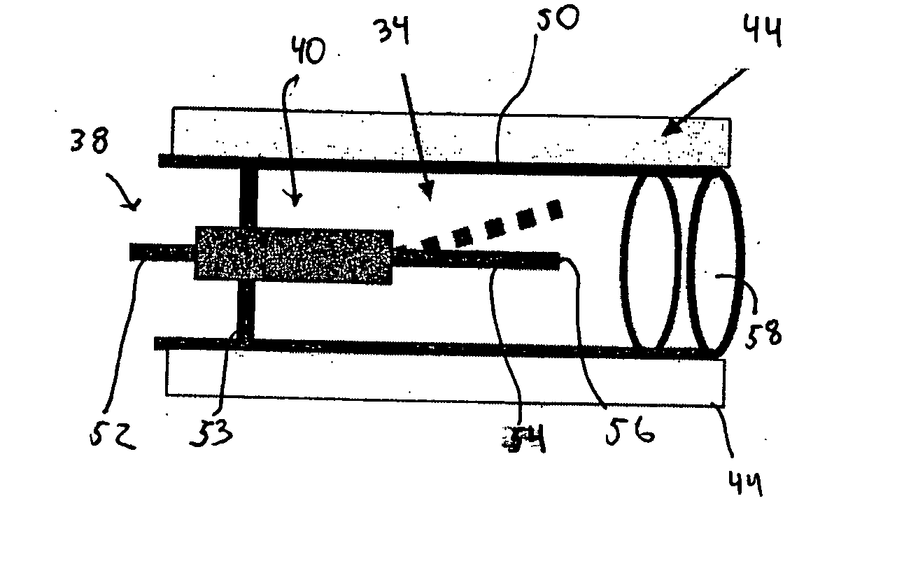
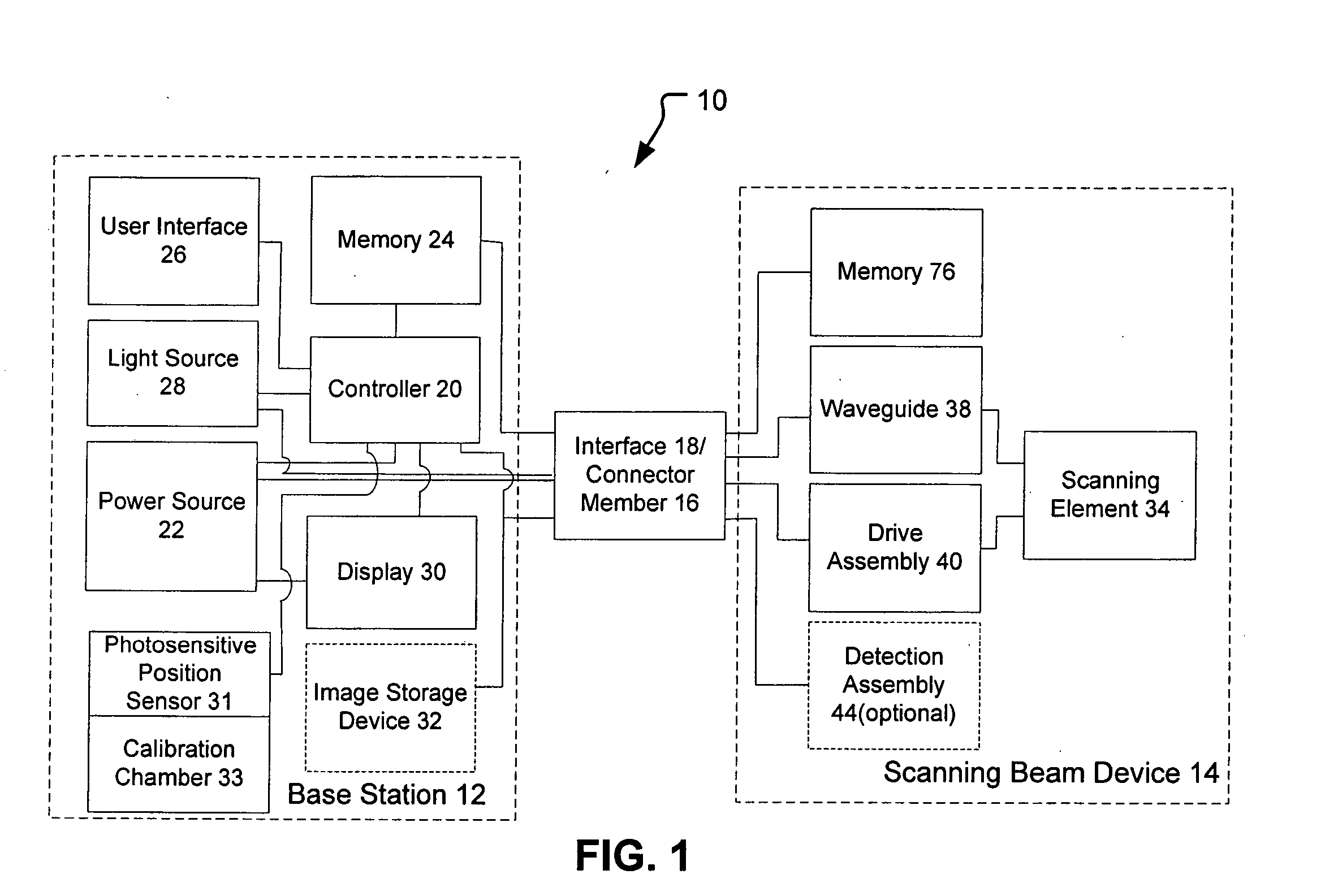
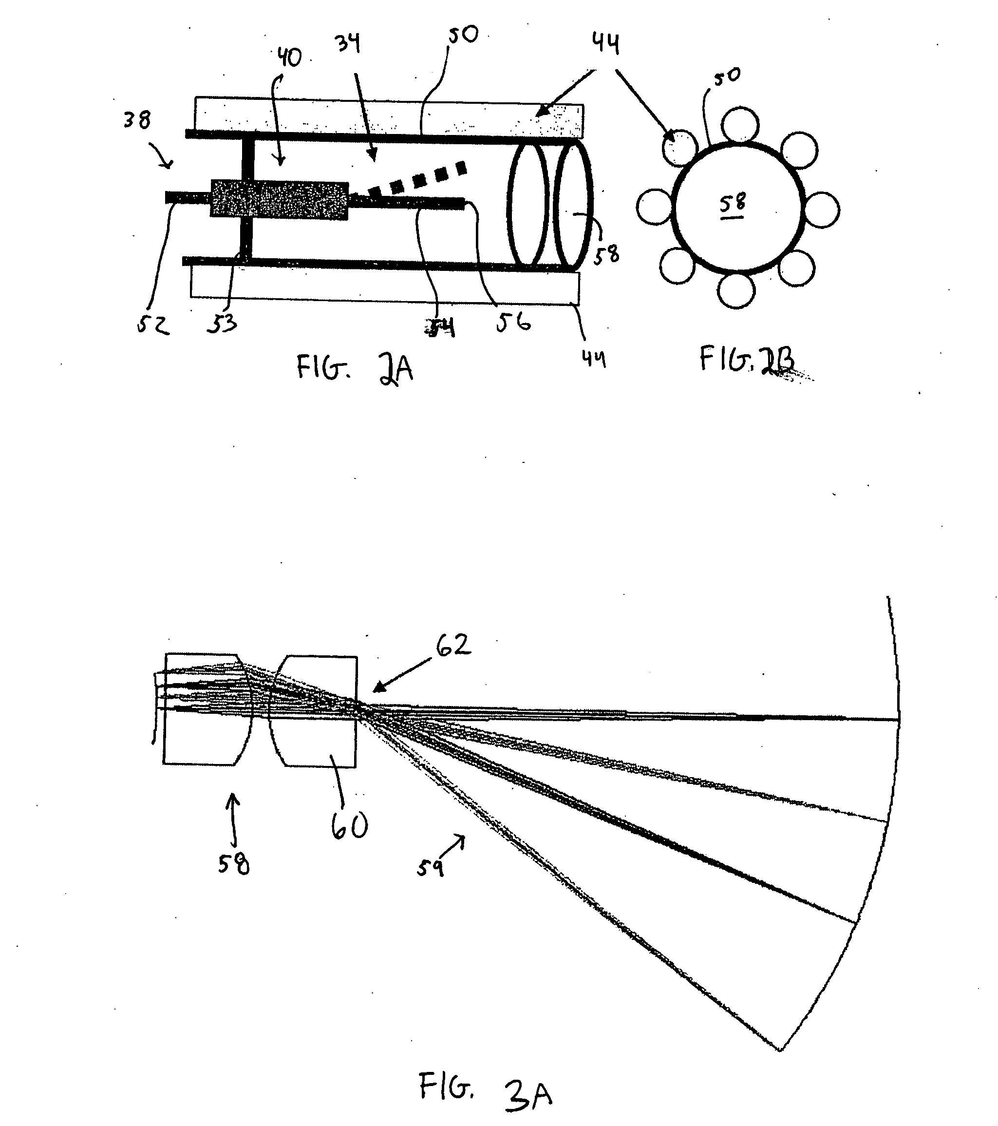
[0008] The present invention provides improved methods and devices of scanning an illumination spot over a target area and collecting the back reflected light. The methods and devices of the present invention typically provide a modified optical assembly that allows the illumination to be directed from a scanning element to the target area and directs the back reflected light from the target area to one or more detectors that are spaced from the scanning element.

Problems solved by technology

Thus, in order to reduce a size of the endoscope, conventional endoscopes must sacrifice image quality, the quality of the optical assembly, and / or durability.

Method used


Image

  • Scanning beam device with detector assembly
  • Scanning beam device with detector assembly
  • Scanning beam device with detector assembly

Examples


Embodiment Construction

[0038] The present invention provides methods and scanning beam devices that scan an illumination spot over a target area and capture reflected light from the target area to generate an image of the target area.

[0039] Scanning beam systems of the present invention include a scanning beam device and a base station for controlling the scanning beam device. The scanning beam devices of the present invention may take on a variety of forms, but are typically in the form of a flexible or rigid endoscope, catheter, fiberscope, microscope, or a boroscope. The scanning beam devices of the present invention may be a limited use device (e.g., disposable device) or a multiple-use device. If the device is for medical use, the scanning beam devices of the present invention will generally be sterile, either being sterilizable or being provided in hermetically sealed package for use.

[0040] The scanning beam devices of the present invention include a scanning element for scanning a beam of light o...


PUM


Abstract

The present invention provides scanning beam devices that have one or more detectors positioned within a housing of the device. The detector(s) may be disposed anywhere within the housing to receive light reflected from the target area. In one embodiment, an optical assembly of the device transmits a first portion of the reflected light to a scanning element, and a second portion of the reflected light to the detectors. In another embodiment, the optical assembly is configured to transmit substantially all of the reflected light to the scanning element. In such embodiments, the scanning element will be adapted to allow the light to exit the scanning element and impinge on the detector(s) within the housing.

Description

BACKGROUND OF THE INVENTION [0001] The present invention relates generally to scanning methods and scanning beam devices. More particularly, the present invention provides improved optical assemblies and improved optical fibers that allow for placement of one or more light detectors within a housing of the scanning beam device. [0002] Conventional endoscopes generally have a separate detector element in its distal tip for every pixel of resolution for the image of the target area. The detector element may be one optical fiber in a fiber bundle or one pixel in a charge coupled device (CCD) or complementary metal oxide semiconductor (CMOS) image detector chip. As the resolution is increased, the number of detector elements must be increased, thus increasing the diameter of the endoscope. Thus, in order to reduce a size of the endoscope, conventional endoscopes must sacrifice image quality, the quality of the optical assembly, and / or durability. [0003] One proposed endoscope that overc...

Claims


Application Information

Patent Timeline
Patent Type & Authority Applications(United States)
IPC IPC(8): H01J3/14
CPCG02B6/262G02B23/2423G02B26/10
Inventor JOHNSTON, RICHARD S.MELVILLE, CHARLES D.
Owner UNIV OF WASHINGTON
Learn More