

Laser microdissection unit
- Summary
- Abstract
- Description
- Claims
- Application Information
AI Technical Summary
Benefits of technology
Problems solved by technology
Method used
Image

Examples
Embodiment Construction
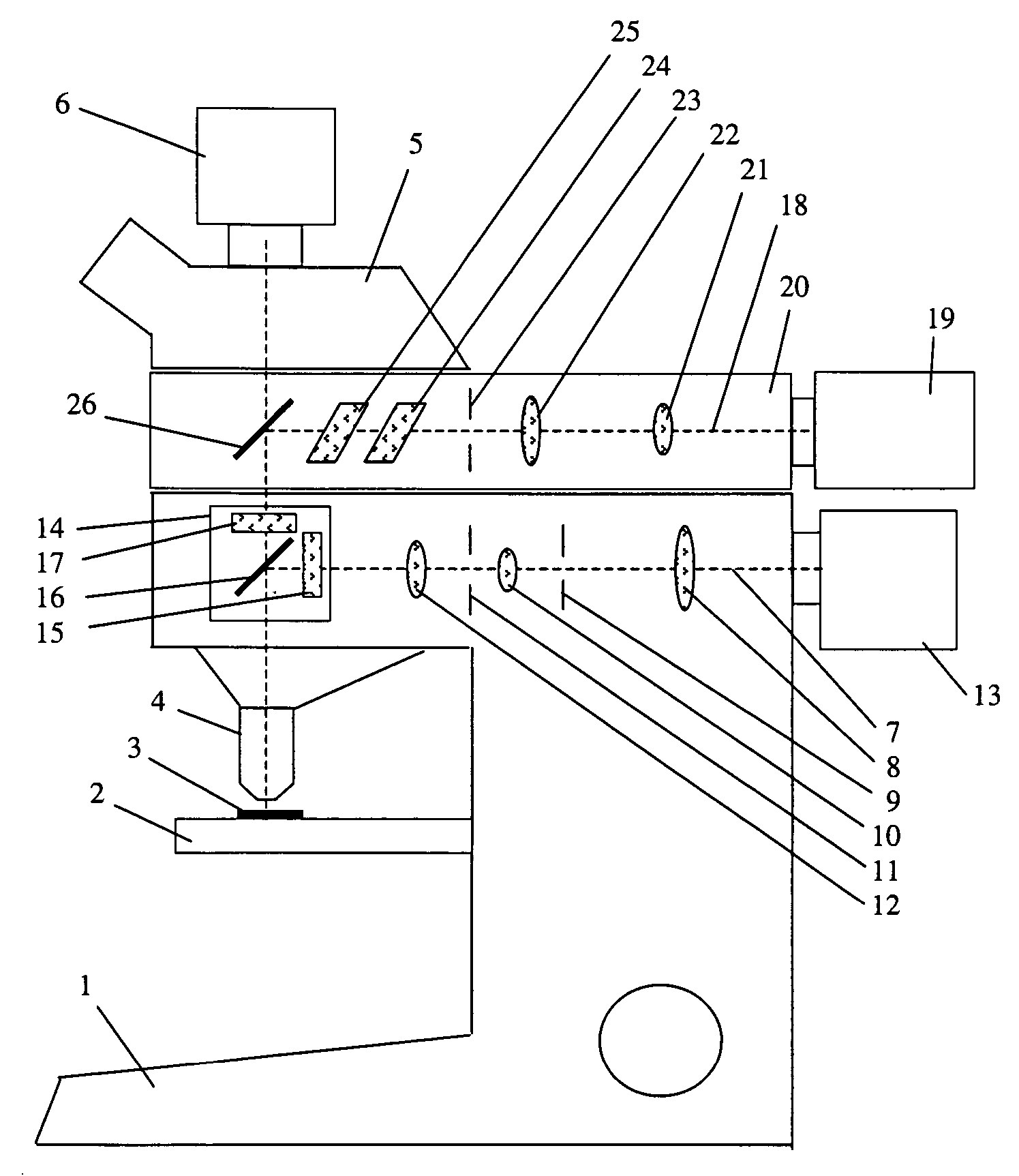
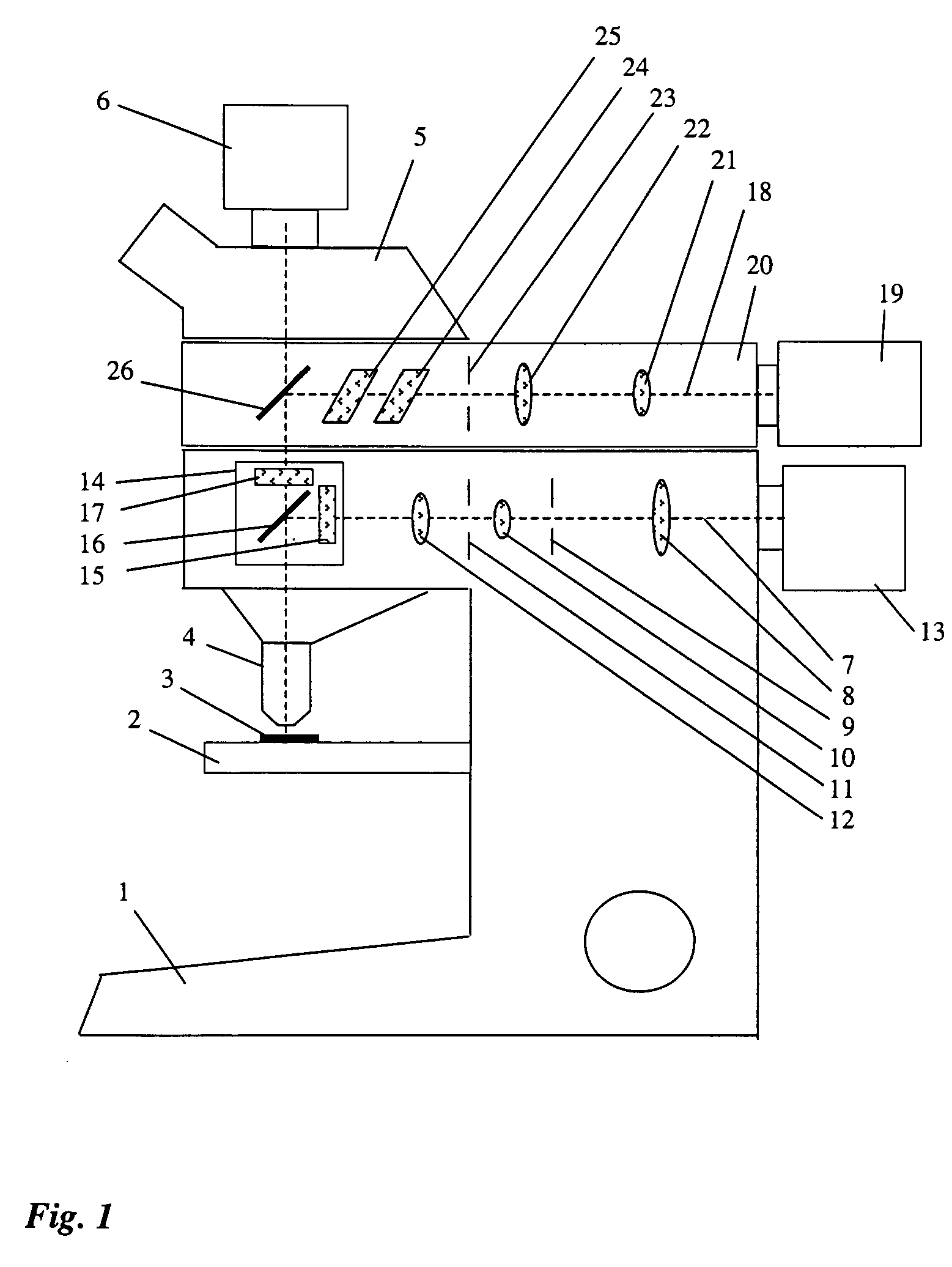
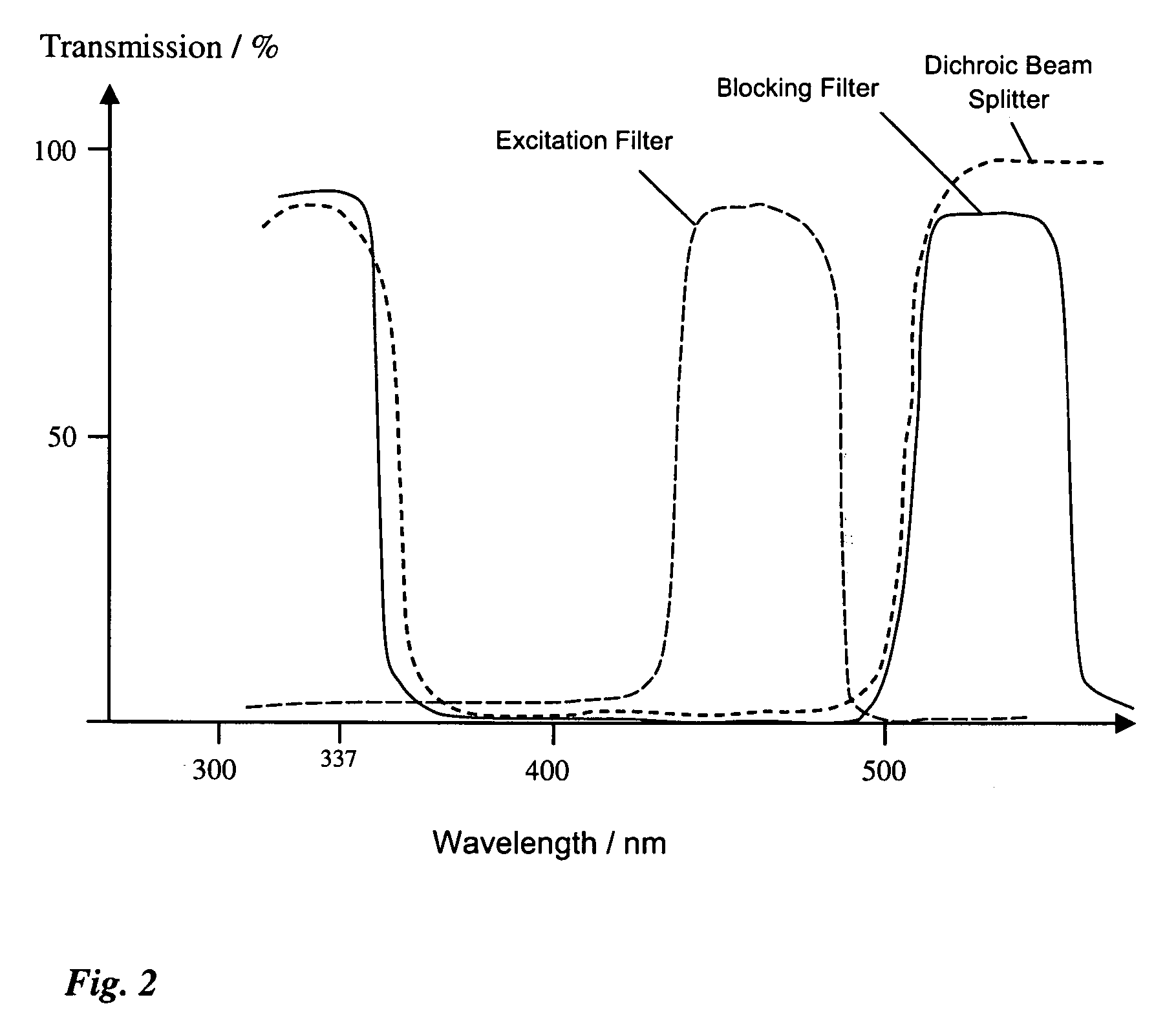
[0018]FIG. 1 shows a laser microdissection unit with a microscope 1. Sample 3 is arranged on microscope stage 2, and is imaged through an objective 4 and a tube 5 onto a camera. Microscope 1 comprises an integrated fluorescence axis 7 in which a lens 8, an aperture diaphragm 9, a lens 10, a field diaphragm 11, and a lens 12 are arranged. The illuminating light proceeding from lamp housing 13 passes along integrated fluorescence axis 7 and strikes fluorescence device 14. The latter encompasses an excitation filter 15, a dichroic beam splitter 16, and a blocking filter 17, which are spectrally matched to at least one fluorescent dye and its fluorescence band.
[0019] A microdissection beam path 18 with a UV laser 19 is arranged above integrated fluorescence axis 7. Microdissection beam path 18 is arranged in a structural unit 20 that is placed onto microscope 1, above integrated fluorescence axis 7, as an attachment.
[0020] The laser beam proceeding from UV laser 19 travels, in microdi...
PUM
 Abstract
Description
Claims
Application Information