Method and device for detecting two parameters of a fluid

Inactive Publication Date: 2006-08-24
ROBERT BOSCH GMBH
View PDF9 Cites 12 Cited by
  • Summary
  • Abstract
  • Description
  • Claims
  • Application Information

AI Technical Summary

Benefits of technology

[0008] An example embodiment of the present invention may provide a method which may provide for different signals to be detected using a single sensor apparatus.

Problems solved by technology

Due to the lack of space in many reaction chambers and supply channels, only a limited number of sensors may be used.
A disadvantage may be that two sensors may be required to determine the permittivity and viscosity of a fluid.

Method used


Image

  • Method and device for detecting two parameters of a fluid
  • Method and device for detecting two parameters of a fluid
  • Method and device for detecting two parameters of a fluid

Examples


Embodiment Construction

[0035] In the Figures, the same reference numerals designate the same or similar components.

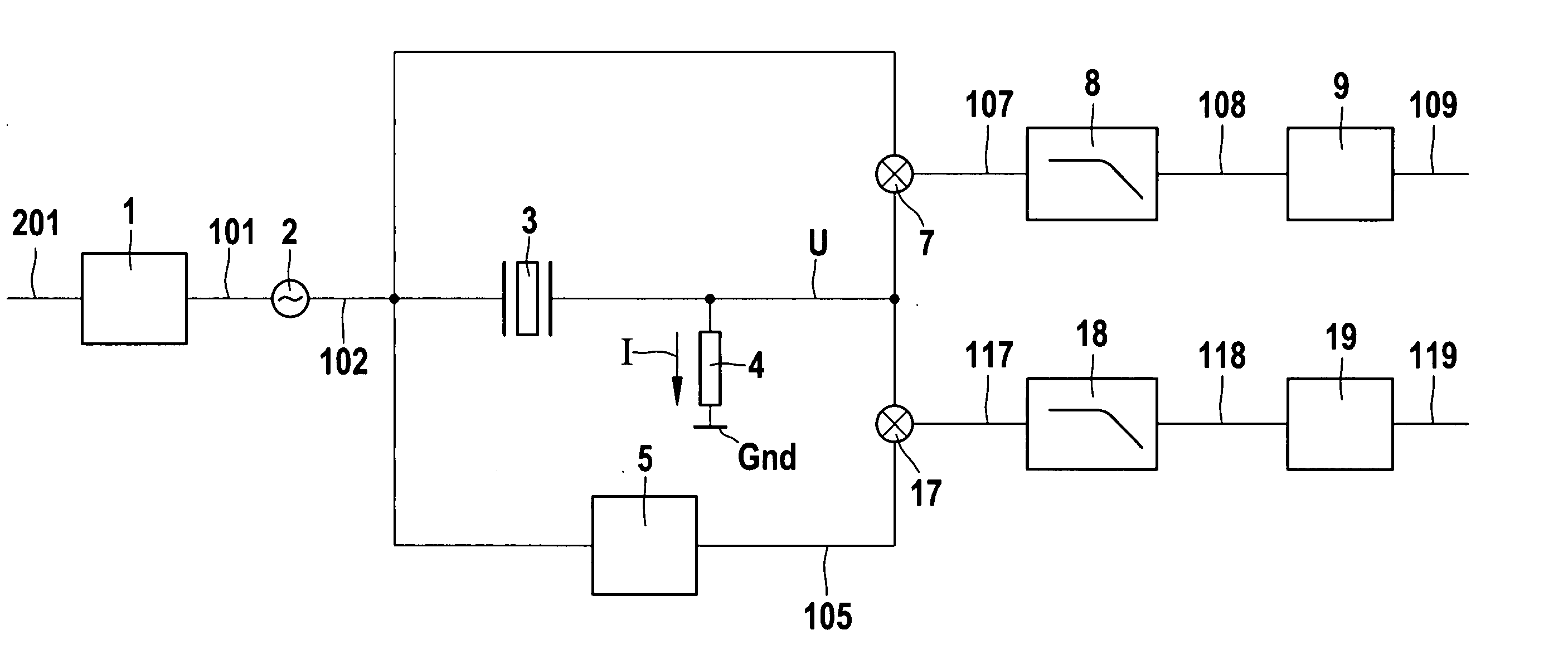
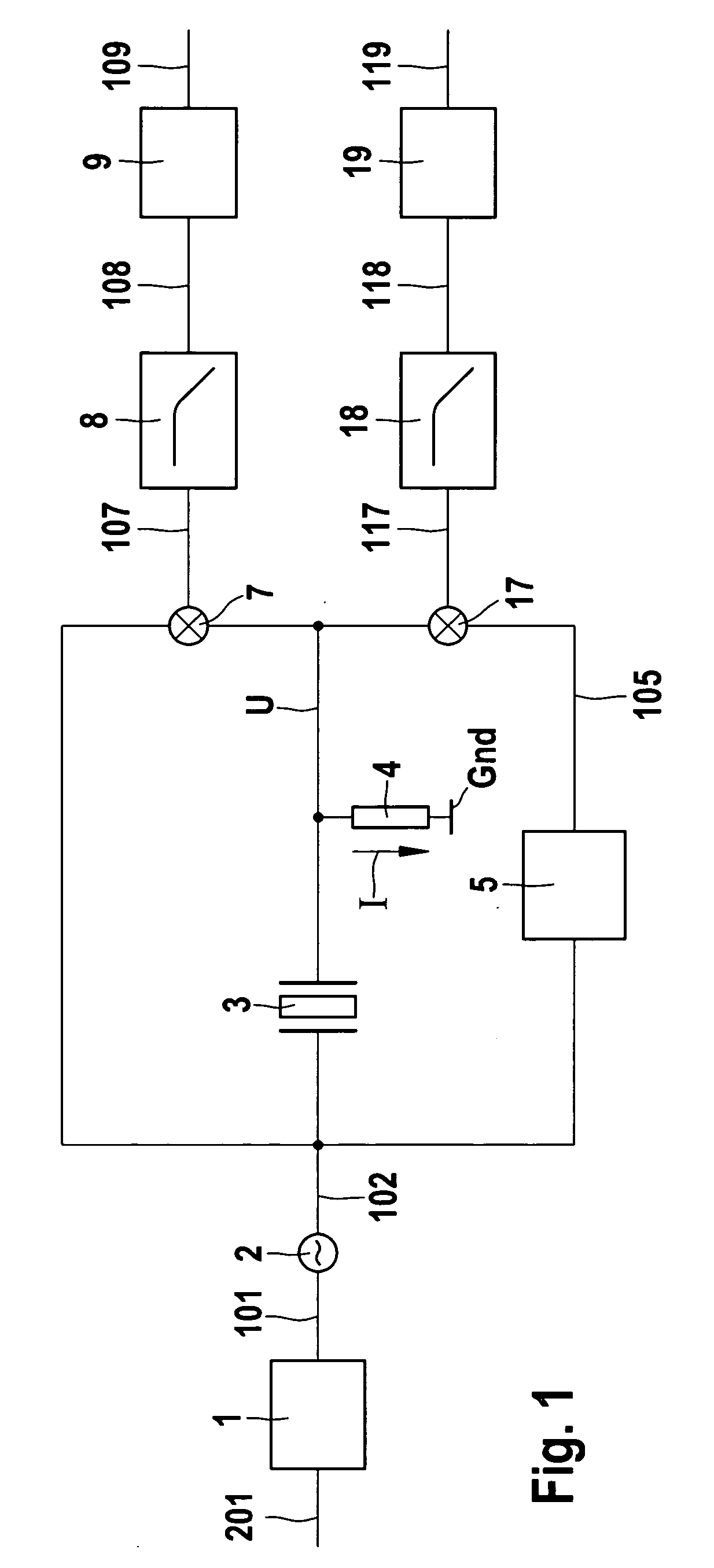
[0036]FIG. 1 is a schematic block diagram of a device of an example embodiment of the present invention. An oscillating circuit 3 is supplied with an excitation signal 102 from a primary oscillation apparatus 2. The excitation signal may be described by sin (wt), where w is the frequency of excitation signal 100 and t is the time. Oscillating circuit 3 is series-connected to a sensor resistor 4, the latter being connected to a ground Gnd. A voltage signal U, which is proportional to current flow I through sensor resistor 4 and oscillating circuit 3, is tapped at a node in oscillating circuit 3 to the sensor resistor. Voltage signal U is hereinafter referred to as the oscillation signal, since it is a measure of the amplitude of the oscillation in oscillating circuit 3. Oscillating circuit 3 includes a quartz. In a similar circuit diagram, the quartz is described by a static capacitance C0 an...


PUM


Abstract

An oscillator is excited by a primary oscillator, and the excited oscillator is immersed in a fluid having two parameters, the first parameter of the fluid damping the excited oscillator via a first phase delay, and the second parameter damping the excited oscillator via a second phase delay. The oscillation of the excited and damped oscillator is detected as the oscillation signal. The oscillation signal is mixed with a phase-shifted signal generated from the excitation signal via a third phase delay which corresponds to either the first or the second phase delay. The mixed signal is averaged over time to determine the first or the second parameter according to the selection of the phase delay.

Description

CROSS-REFERENCE TO RELATED APPLICATIONS [0001] The present application claims priority to Application No. 10 2005 007 544.4, filed in the Federal Republic of Germany on Feb. 18, 2005, which is expressly incorporated herein in its entirety by reference thereto. FIELD OF THE INVENTION [0002] The present invention relates to a method and a device for detecting two parameters of a fluid. In particular, the present invention relates to the detection of the parameters via a sensor apparatus having an excited oscillator. BACKGROUND INFORMATION [0003] The detection of physical properties and assigned variables (parameters) of a fluid, such as viscosity and permittivity, makes it possible to draw conclusions as to the chemical reactions in progress and the course thereof as well as to determine physical properties such as the mixing ratio of two fluids. Due to the lack of space in many reaction chambers and supply channels, only a limited number of sensors may be used. Sensors and devices fo...

Claims


Application Information

Patent Timeline
IPC IPC(8): G01R27/04G01R27/32
CPCG01N11/16G01N27/228G01N2011/0066
Inventor NIEMANN, MARKUS
Owner ROBERT BOSCH GMBH
Why Eureka
Try Eureka