Backlight driver circuit and liquid crystal display device having the same

Inactive Publication Date: 2006-08-24
SAMSUNG MOBILE DISPLAY CO LTD
View PDF9 Cites 60 Cited by
  • Summary
  • Abstract
  • Description
  • Claims
  • Application Information

AI Technical Summary

Benefits of technology

[0011] The present invention also provides a field sequential LCD device having a backlight driver circuit capable of supplying driving currents suitable for respective light emitting diodes, and of reducing power consumption.

Problems solved by technology

In this regard, since the same driving voltage is supplied during three sub-frames corresponding to one frame for driving the R, G and B light emitting diodes, the driving voltage generator should generate the highest driving voltage among the driving voltages needed for the R, G and B light e

Method used


Image

  • Backlight driver circuit and liquid crystal display device having the same
  • Backlight driver circuit and liquid crystal display device having the same
  • Backlight driver circuit and liquid crystal display device having the same

Examples


Embodiment Construction

[0026] Hereinafter, exemplary embodiments of the present invention will be described with reference to the accompanying drawings.

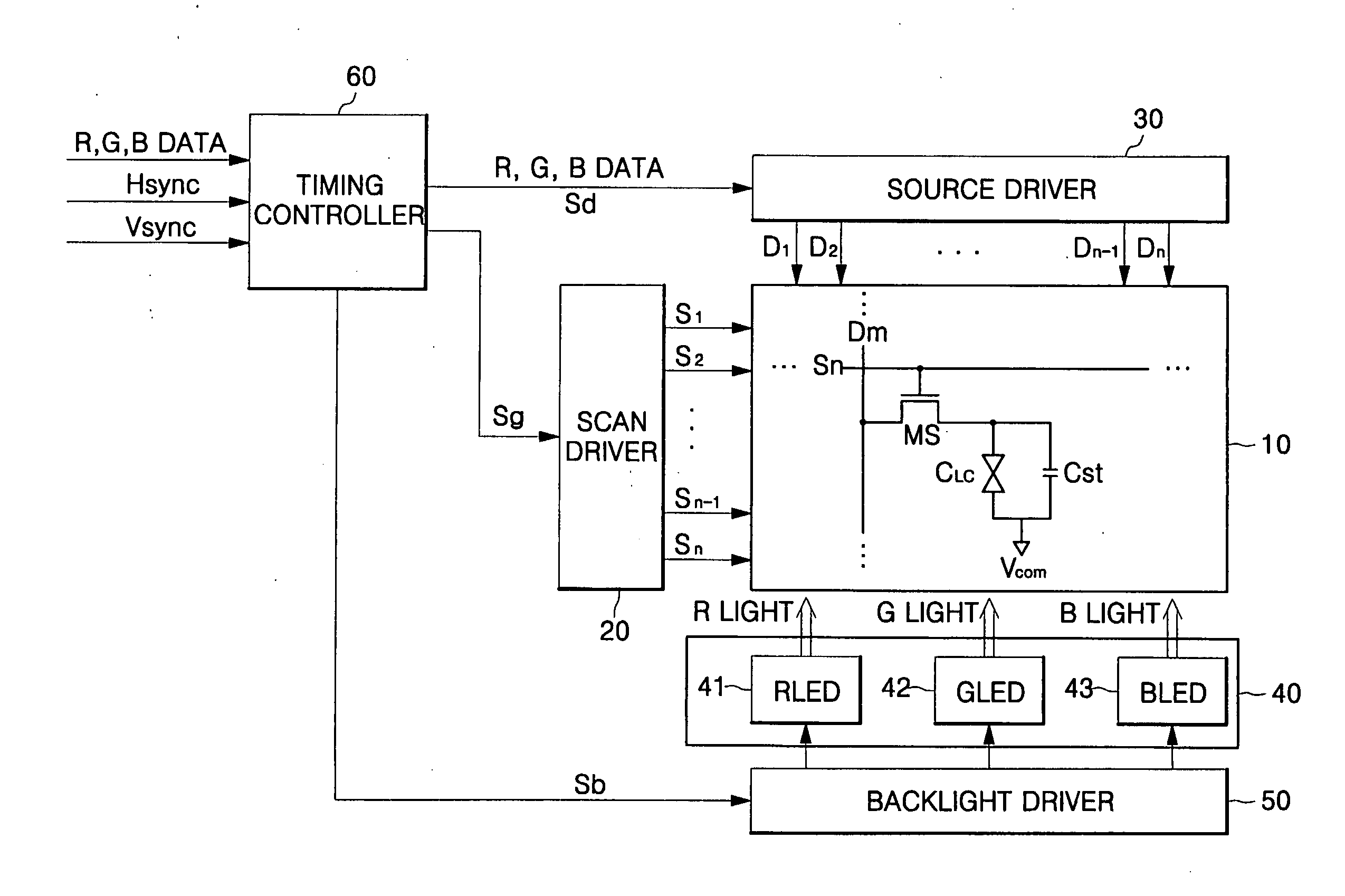
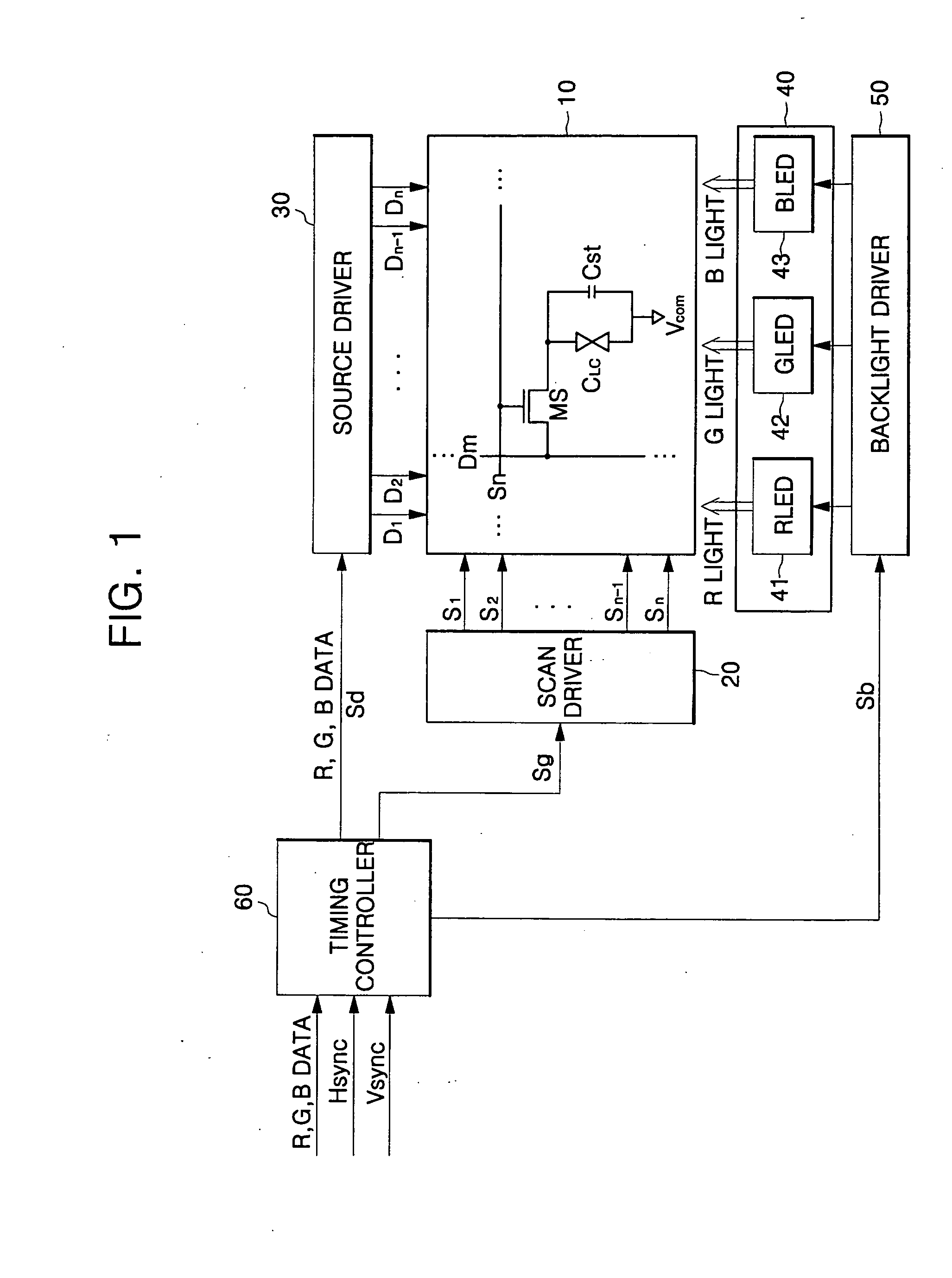
[0027]FIG. 1 is a block diagram of a field sequential liquid crystal display (LCD) device.

[0028] Referring to FIG. 1, the LCD device includes an LCD panel 10 having a lower substrate (not shown), an upper substrate (not shown), and a liquid crystal (not shown) sandwiched between the upper and lower substrates. The lower substrate is formed with a thin film transistor (TFT) array having a switching thin film transistor MS connected to a plurality of scan lines S1 thru Sn and a plurality of data lines D1 thru Dm, and the upper substrate is formed with a common electrode to supply a common voltage to a common line.

[0029] Furthermore, the LCD device comprises: a scan driver 20 for supplying a scan signal to the plurality of scan lines S1 thru Sn of the LCD panel 10; a source driver 30 for supplying R, G and B data signals to the plurality of data lines D1 t...


PUM


Abstract

In a backlight driver circuit and a liquid crystal display (LCD) device employing the same, separate forward driving currents are applied to red (R), green (G) and blue (B) backlights, respectively, thereby overcoming the problem of brightness variation resulting from forward voltage Vf variation in a light emitting diode (LED). The LCD includes: a backlight unit provided with R, G and B backlights for emitting light toward an LCD panel in sequence; and a backlight driver for supplying driving currents and pulse width modulation (PWM) signals to the backlight unit so as to control brightness and chromaticity of the R, G and B backlights. The backlight driver includes: a driving current generator for supplying R, G and B driving currents to the respective R, G and B backlights, and for causing the respective R, G and B backlights to emit light with predetermined brightness; and a PWM signal generator for supplying R, G and B PWM signals to the R, G and B backlights, respectively, so as to adjust the chromaticity of the light emitted from the R, G and B backlights, respectively.

Description

CLAIM OF PRIORITY [0001] This application makes reference to, incorporates the same herein, and claims all benefits accruing under 35 U.S.C. § 119 from an application earlier filed in the Korean Intellectual Property Office on Feb. 22, 2005 and there duly assigned Serial No. 2005-14698. BACKGROUND OF THE INVENTION [0002] 1. Technical Field of the Invention [0003] The present invention relates to a liquid crystal display (LCD) device, and more particularly, to a backlight driver circuit and an LCD device having the same, in which a forward driving current is applied to red (R), green (G), and blue (B) backlights, thereby improving brightness variation in response to a forward voltage Vf applied to a light emitting diode (LED). [0004] 2. Related Art [0005] In general, a color liquid crystal display (LCD) device includes: an LCD panel having an upper substrate, a lower substrate, and a liquid crystal disposed between the upper and lower substrates; a driver circuit for driving the LCD ...

Claims


Application Information

Patent Timeline
IPC IPC(8): G09G3/36
CPCG09G3/3413G09G2310/0235G09G2320/041G09G2320/0633G09G2320/064G09G2320/0666G09G2330/021E03C1/182E03C1/23E03C2001/2317
Inventor KIM, TAE-SOO
Owner SAMSUNG MOBILE DISPLAY CO LTD
Why Eureka
Try Eureka