Methods and apparatus for spatial light modulation

a technology of spatial light and modulation method, applied in the field of spatial light modulation, can solve the problems of reducing the optical efficiency to about 5%, combining mechanical apertures with color filters, and not demonstrating sufficiently attractive combinations of brightness and low power, so as to improve the brightness of the display, improve the transmittance or optical efficiency of mechanical modulators coupled to backlights, and improve the effect of luminous efficiency

Active Publication Date: 2006-08-24
SNAPTRACK
View PDF99 Cites 123 Cited by
  • Summary
  • Abstract
  • Description
  • Claims
  • Application Information

AI Technical Summary

Benefits of technology

[0004] The devices and methods described herein provide for mechanical light modulators having improved luminous efficiency, making mechanical actuators attractive for use in portable and large area displays. In some cases, the transmittance or optical efficiency of mechanical modulators coupled to backlights can be improved to the 40 to 60% level, or 10 times more efficient than what is typical in a liquid crystal display. In addition, the devices and methods described herein can be incorporated into small-size, high resolution displays, regardless of the light modulation mechanism, to improve the brightness of the displays and to reduce the power requirements in a display application.

Problems solved by technology

Backlit displays using mechanical light modulators have not yet demonstrated sufficiently attractive combinations of brightness and low power.
Combining the mechanical apertures with color filters reduces the optical efficiency to about 5%, i.e., no better than the efficiencies available in current color liquid crystal displays.

Method used


Image

  • Methods and apparatus for spatial light modulation
  • Methods and apparatus for spatial light modulation
  • Methods and apparatus for spatial light modulation

Examples


Embodiment Construction

[0037] To provide an overall understanding of the invention, certain illustrative embodiments will now be described, including apparatus and methods for spatially modulating light. However, it will be understood by one of ordinary skill in the art that the systems and methods described herein may be adapted and modified as is appropriate for the application being addressed and that the systems and methods described herein may be employed in other suitable applications, and that such other additions and modifications will not depart from the scope hereof.

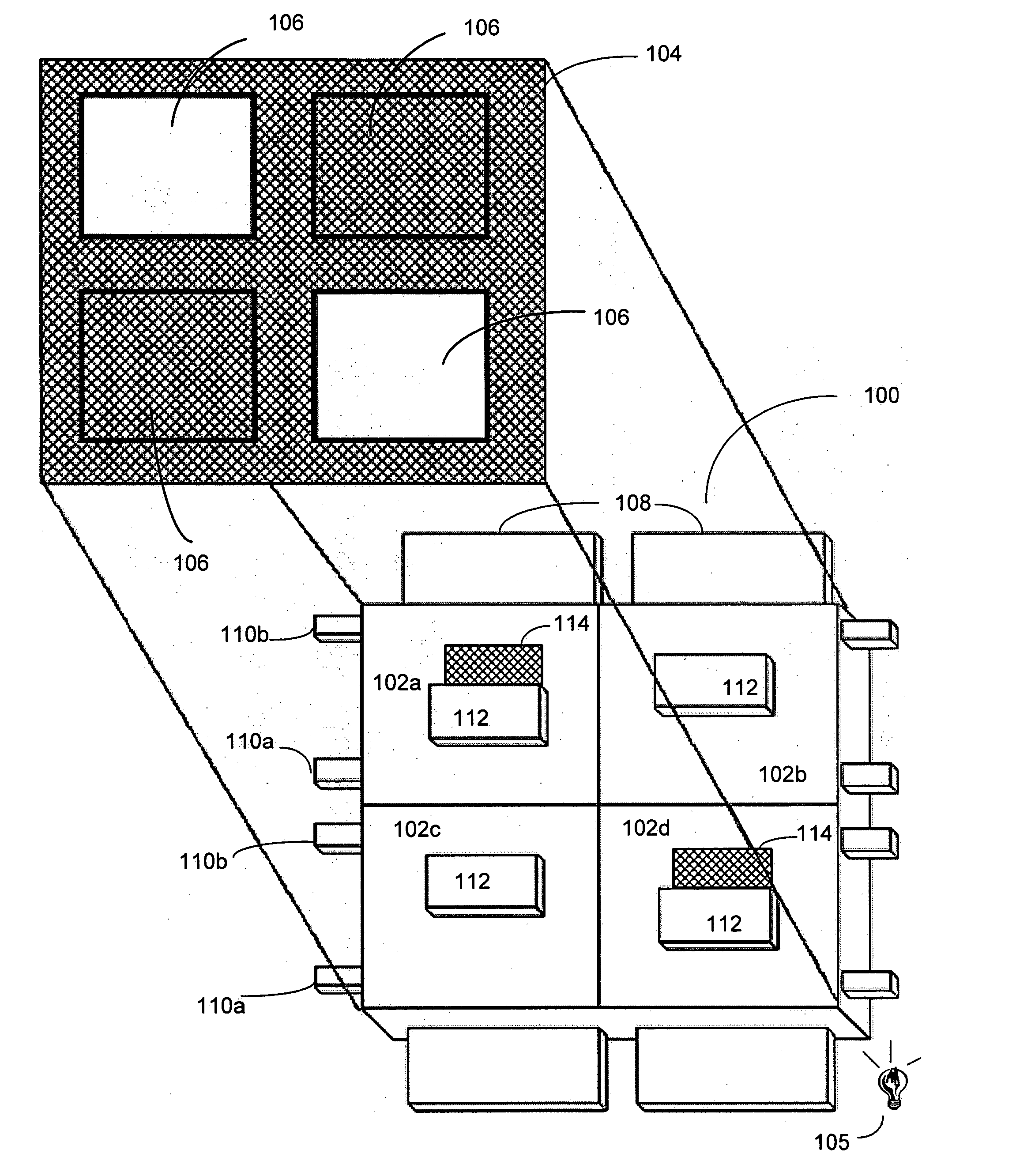
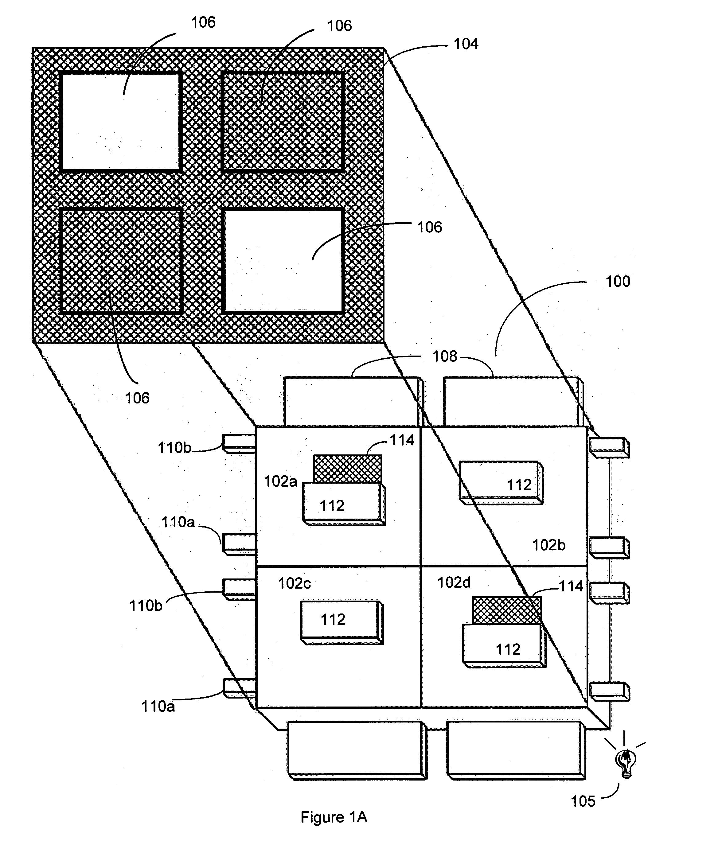
[0038]FIG. 1A is an isometric conceptual view of an array 100 of light modulators (also referred to as a “light modulation array 100”), according to an illustrative embodiment of the invention. The light modulation array 100 includes a plurality of shutter assemblies 102a-102d (generally “shutter assemblies 102”) arranged in rows and columns. In general, a shutter assembly 102 has two states, open and closed (although partial openin...


PUM


Abstract

Improved apparatus and methods for spatial light modulation are disclosed which utilize optical cavities having both front and rear reflective surfaces. Light-transmissive regions are formed in the front reflective surface for spatially modulating light.

Description

CROSS-REFERENCE TO RELATED APPLICATIONS [0001] This application incorporates by reference in entirety, and claims priority to and benefit of, U.S. Provisional Patent Application No. 60 / 676,053, entitled “MEMS Based Optical Display” and filed on Apr. 29, 2005; and U.S. Provisional Patent Application No. 60 / 655,827, entitled MEMS Based Optical Display Modules” and filed on Feb. 23, 2005.FIELD OF THE INVENTION [0002] In general, the invention relates to the field of spatial light modulation, in particular, the invention relates to displays having improved backlights. BACKGROUND OF THE INVENTION [0003] Displays built from mechanical light modulators are an attractive alternative to displays based on liquid crystal technology. Mechanical light modulators are fast enough to display video content with good viewing angles and with a wide range of color and grey scale. Mechanical light modulators have been successful in projection display applications. Backlit displays using mechanical light...

Claims


Application Information

Patent Timeline
Patent Type & Authority Applications(United States)
IPC IPC(8): G02B26/08
CPCG02B6/0043G02B6/0046G02B26/02G02B6/0078G02B6/0061
Inventor HAGOOD, NESBITT W.BARTON, ROGER W.
Owner SNAPTRACK
Why Eureka
Try Eureka