Polarized light irradiation apparatus polarized light irradiation method, photo alignment film, and retardation film

a technology of polarized light and irradiation apparatus, which is applied in the direction of polarising elements, point-like light sources, instruments, etc., can solve the problems of difficult to obtain polarized light in a large area, static electricity generation, and dust generation, and achieve uniform optical properties and uniform alignment ability.

Inactive Publication Date: 2006-08-24
DAI NIPPON PRINTING CO LTD
View PDF7 Cites 8 Cited by
  • Summary
  • Abstract
  • Description
  • Claims
  • Application Information

AI Technical Summary

Benefits of technology

[0022] e) a process of irradiating the irradiation target substrate with a polarized light obtained by passing the projection light through the polarizer, while the subject as the irradiation target is transported in a direction perpendicular to a straight line including a projection image which is obtained by projecting an incident plane of a light entering at the Brewster angle among the projection light onto the substrate. According to the present invention, since there is provided with the process of irradiating the irradiation target substrate with the polarized light obtained by passing the projection light through the polarizer, while the irradiation target substrate is transported in a direction perpendicular to the straight line including the projection image which is obtained by projecting the incident plane of the light entering at the Brewster angle onto the substrate, it is possible to provide the alignment ability for the alignment film, even if using the polarized light having the symmetrically diverged polarization axes obtained by passing the projection light including a non-parallel light through the polarizer comprising plates disposed in parallel with each other and at a tilt by Brewster angle.
[0023] Furthermore, the present invention provides a photo alignment film produced by means of the polarized light irradiation apparatus or method according to the present invention mentioned above. The photo alignment film of the present invention is advantageous in view of process in that it has inherently no problem involved in the rubbing process such as a generation of static electricity due to triboelectrification or a generation of dust from cloths or the like, and it can be provided with a uniform alignment ability without using a highly parallelized light.
[0024] Also, the present invention provides a retardation film produced by means of the polarized light irradiation apparatus or method according to the present invention mentioned above. The retardation film of the present invention is advantageous in view of process in that it has inherently no problem involved in the rubbing process such as a generation of static electricity due to triboelectrification or a generation of dust from cloths or the like, and it can be uniformly aligned and thereby have a uniform optical property without using a highly parallelized light.

Problems solved by technology

In such a rubbing process, however, there are several inherent problems such as a generation of static electricity due to triboelectrification, and a generation of dust from cloths or the like.
However, the above-mentioned prism polarizer is difficult to obtain itself in a large size and thereby difficult to obtain polarized light in a large area.
Also, the above-mentioned polarizing film using a material exhibiting its dichroism in an ultraviolet range has a problem of durability due to exothermic heat or deterioration involved in light absorption from an ultraviolet light source.
Furthermore, in a system using the polarizer based on Brewster angle, there is a problem of divergence of polarization axes in the case of divergent beam, because a polarizing direction depends on an incident angle of an incident light.
Additionally, there is a limit to obtain a large area.

Method used


Image

  • Polarized light irradiation apparatus polarized light irradiation method, photo alignment film, and retardation film
  • Polarized light irradiation apparatus polarized light irradiation method, photo alignment film, and retardation film
  • Polarized light irradiation apparatus polarized light irradiation method, photo alignment film, and retardation film

Examples


example 1

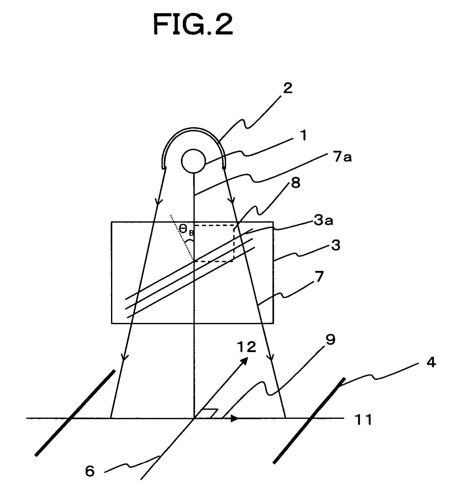
[0093] A ultraviolet (hereinafter referred to as LW) light source using a high pressure mercury lamp (TOSCURE 751 available from HARISON TOSHIBA LIGHTING Corp.) was used as a light source. A projection light including a non-parallel light formed by means of this light source and an ellipsoidal condenser mirror was entered a polarizer made of 25 quartz plates disposed in parallel with each other at a predetermined interval so that a center part of the projection light including a non-parallel light enters from a direction of Brewster angle. A divergence angle of the projection light from the light source was about 10 degrees. The polarization axis on the substrate had an angle −7 degrees at the uppermost stream of the irradiation region and an angle +7 degrees at the lowermost stream, provided that the center part, which was to be a straight line including a projection image onto the substrate of an incident plane of the light entering at Brewster angle, has an angle 0 degree. The ex...


PUM


Abstract

The main object of the invention is to provide a polarized light irradiation apparatus capable of providing a uniform alignment ability for an alignment film without using a highly parallelized light, and capable of conducting a photo-alignment in a larger area efficiently, and having an excellent durability. To this end, there is proposed a polarized light irradiation apparatus comprising: a light source; a projection device for projecting a light from the light source as a projection light including a non-parallel light; a polarizer for passing the projection light therethrough and comprising one glass plate disposed at a tilt by Brewster angle relative to an incident direction of a center part of the projection light, or comprising a plurality of glass plates disposed in parallel with each other at a predetermined interval and at a tilt by Brewster angle relative to the incident direction of the center part of the projection light; and a substrate transportation device for transporting an irradiation target substrate in a direction perpendicular to a straight line including a projection image which is obtained by projecting an incident plane of a light entering at the Brewster angle among the projection light onto the substrate.

Description

BACKGROUND OF THE INVENTION [0001] 1. Field of the Invention [0002] The present invention relates to a polarized light irradiation apparatus and a polarized irradiation method suitably used for photo-aligning an alignment film of a liquid crystal display device by irradiating such a film with polarized light. The present invention further relates to a photo alignment film and a retardation film produced by using such apparatus and method. [0003] 2. Description of the Related Art [0004] A liquid crystal display device is typically constructed from two substrates. On one of these two substrates, there are provided with a drive device (e.g. thin film transistor known as TFT), an electrode made of a transparent conductive film for driving a liquid crystal, and an alignment film for aligning a liquid crystal in a specific direction, and so on. On the other substrate, there are provided with a light shielding film referred to as “black matrix”, a color filter (in the case of a color liqui...

Claims


Application Information

Patent Timeline
Patent Type & Authority Applications(United States)
IPC IPC(8): G02B27/28G02B5/30F21Y101/00
CPCG02B5/3066G02F1/133788G02F1/1337
Inventor FUKUDA, MASANORI
Owner DAI NIPPON PRINTING CO LTD
Why Eureka
Try Eureka