
Method for the control of door and window adjusting parameters of a driven motor vehicle sliding door with a window and control system for the execution of the method

Inactive Publication Date: 2006-08-31
BROSE FAHRZEUGTEILE GMBH & CO KG
View PDF6 Cites 26 Cited by
  • Summary
  • Abstract
  • Description
  • Claims
  • Application Information

AI Technical Summary

Benefits of technology

[0010] The present invention is directed to a method and control system therefore which provide increased crush protection and overall increased safety against the above described dangers associated with sliding doors and windows. An additional feature of the present invention is its relative simplicity thereby facilitating flexible application and reduced costs.

Problems solved by technology

If the window is fully or partially open, a further crush situation can occur during the opening process of the sliding door.
With the traveling element in the form of a window pane on the adjusting range of the motor-driven sliding door, new risks arise regarding potential crush incidents in the window and in particular in the door adjusting range.

Method used


Image

  • Method for the control of door and window adjusting parameters of a driven motor vehicle sliding door with a window and control system for the execution of the method
  • Method for the control of door and window adjusting parameters of a driven motor vehicle sliding door with a window and control system for the execution of the method
  • Method for the control of door and window adjusting parameters of a driven motor vehicle sliding door with a window and control system for the execution of the method

Examples


first embodiment

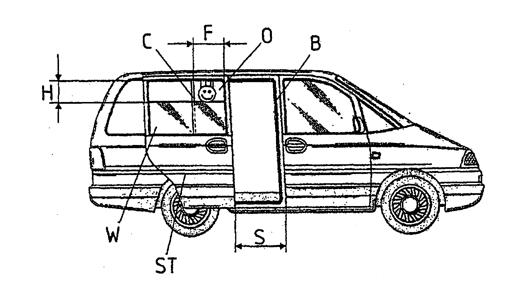
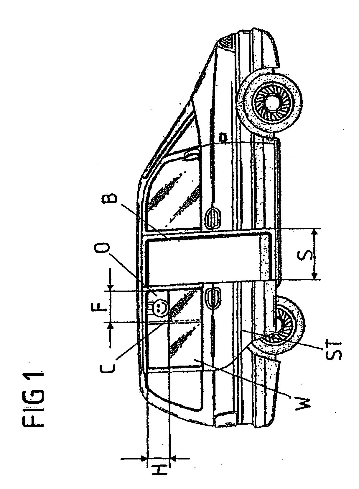
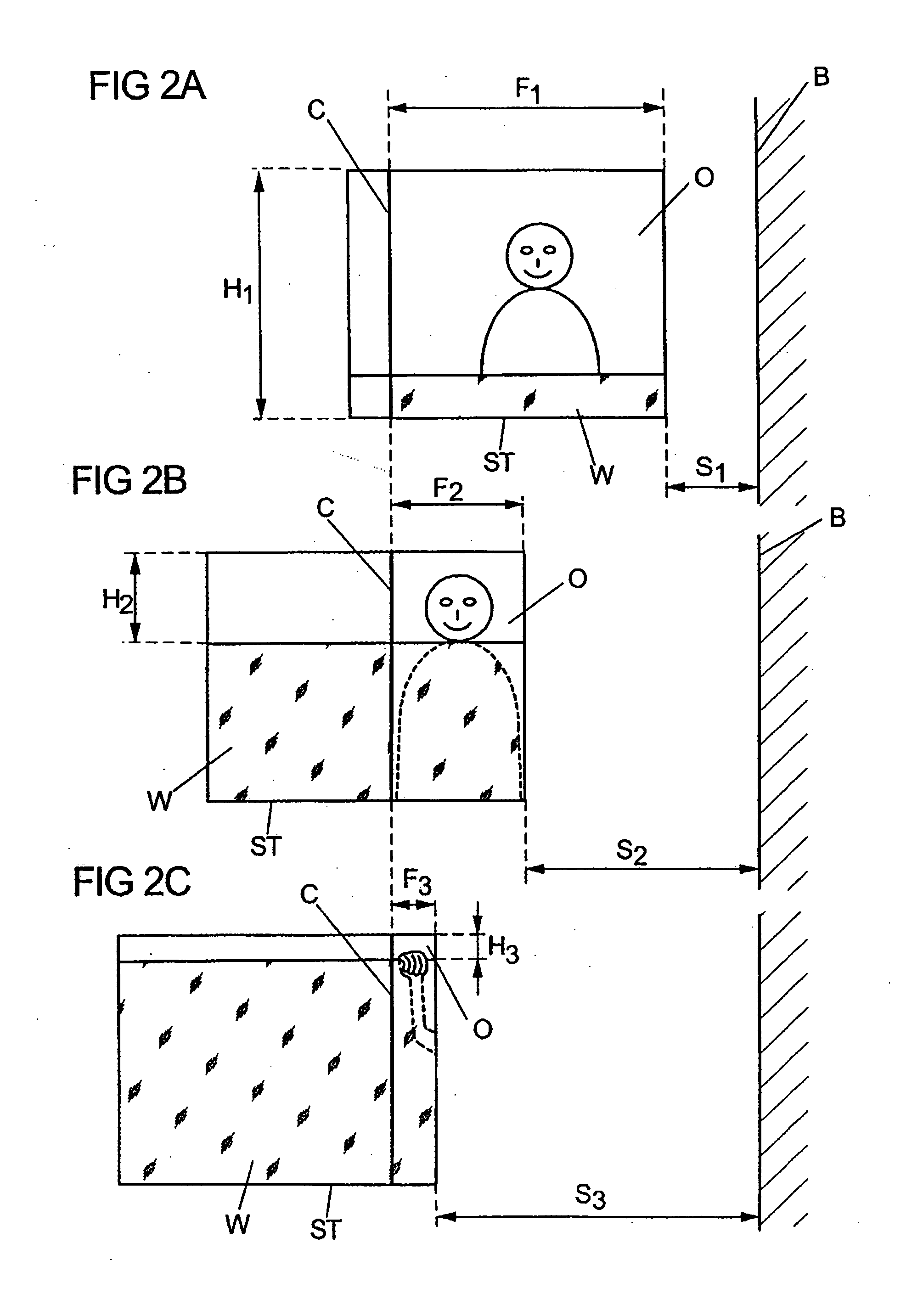
[0087] In the currently described first embodiment of the present invention, the sensors of the sensory system K3 are arranged completely on the side of the door. The characteristic door-side is to be understood as the sensors K30 and K31 belonging to the sensory system K3 arranged at the sliding door K10. However, this does not exclude further components of the sensory system K3, for example appropriate evaluation electronics, from being arranged on the side of the motor vehicle of the vehicle and therefore not in the door-side.

[0088] The sensory system K3 comprises on the one hand a B sensor K30 for the detection of an object, which is at least a partially opened sliding door K10 between the B column KB of the motor vehicle and the boundary edge of the sliding door K10 facing the B column KB of the motor vehicle. The B sensor K30 extends therefore along the entire boundary edge of the sliding door K10. Such a scenario will be described as a B-crush case herein below.

[0089] On the...

second embodiment

[0101] The sensor system is developed according to the sensor system of the second embodiment depicted in FIG. 6, with B-sensor K30 and C-sensor K31 on the side of the motor vehicle body.

[0102] The sensors K30 and K31 on the side of the motor vehicle body are not appropriate to detect obstacles in the window adjusting range KF. The sensor system K3 therefore comprises a crush protection of the window lifter control electronics K2 function according to previous embodiments, as a functional component or a crush sensor developed as a separate component along the closing edge of the window frame.

[0103] Another embodiment of the control system is depicted in FIGS. 8A and 8B, with the sensors K30, K31 and K32, of the sensor system K3, arranged exclusively on the side of the door. The single piece development of the B sensor K30 and C sensor K31 corresponds to the above described embodiments depicted FIGS. 5A and 5B.

[0104] Furthermore, a window sensor K32 extends along the window frame o...


PUM


Abstract

A method for control of door and window adjusting parameters is disclosed, the method including the steps: determining at least a first door adjusting parameter and at least a first window adjusting parameter, controlling the first door adjusting parameter and a further door adjusting parameter by considering the determined first window adjusting parameter and controlling the first window adjusting parameter and a further window adjusting parameter by considering the determined first door adjusting parameter. The above steps may also be performed in the alternative. An interaction between the two moveable elements sliding door and window pane is assured. The control of further parameters can occur in dependence from the determined parameters in such way that the risk of arising injuries and in particular damages by a crush incident between a C column of the motor vehicle and the sliding door at a window opening of the sliding door is minimized.

Description

BACKGROUND OF THE INVENTION [0001] The present invention is directed to a method for controlling door and window adjusting parameters of an actuated motor vehicle sliding door having a window located therein. Either or both of the window and door may be powered. [0002] Increasingly, motor vehicles make use of motor drives for opening and closing sliding doors. Typically, such sliding doors are placed between B and C columns of a motor vehicle, such that, when closed, the sliding doors lock the respective motor vehicle body section. [0003] In the present description, the motor vehicle body sections which apply to the B and C columns, placed to the vertical sliding door edges and adjacent one another at a closed sliding door, are independent of whether they are the actual B and C column of the motor vehicle. A sliding door may, for example, be located between the C and D column of a motor vehicle. It is further possible that respective windows of sliding doors and adjacent window or w...

Claims


Application Information

Patent Timeline
IPC IPC(8): E05F15/02
CPCB60J5/06E05Y2900/531E05Y2900/55E05Y2400/53E05F2015/483E05F15/646E05F15/689E05F15/70E05F15/43
Inventor HERWIG, ARNDKRIESE, OLAFFRANEK, STEFAN
Owner BROSE FAHRZEUGTEILE GMBH & CO KG
Features
  • Generate Ideas
  • Intellectual Property
  • Life Sciences
  • Materials
  • Tech Scout
  • Unparalleled Data Quality
  • Higher Quality Content
  • 60% Fewer Hallucinations
Learn More