Electric power generation system for vehicle

Inactive Publication Date: 2006-08-31
DENSO CORP
View PDF14 Cites 94 Cited by
  • Summary
  • Abstract
  • Description
  • Claims
  • Application Information

AI Technical Summary

Problems solved by technology

Recently, a growing number of auxiliary apparatus or devices mounted on a vehicle and of functions thereof has increased the amount of current power consumption or a dark current while the vehicle is in idle or stops.
A vehicle which does not run for a long time causes a remarkable voltage loss of the battery.
This phenomenon further decreases the capacity of the secondary battery because the balance between the charging and discharging is affected by the increase or change of electric load of the vehicle during driving.
If an excess of discharging occurs in the battery, it becomes difficult to start the internal combustion engine.
However, this conventional manner introduces the limitation caused by increasing a weight and volume of the battery.
However, the conventional technique (1) described above has still a drawback to discharge the electric power accumulated in the battery at the stopping of the el

Method used


Image

  • Electric power generation system for vehicle
  • Electric power generation system for vehicle
  • Electric power generation system for vehicle

Examples


first embodiment

[0031] A description will now be given of the electric power generation system for vehicle according to the first embodiment of the present invention.

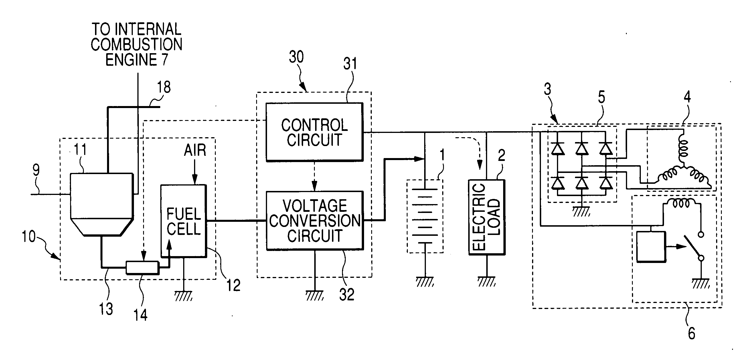
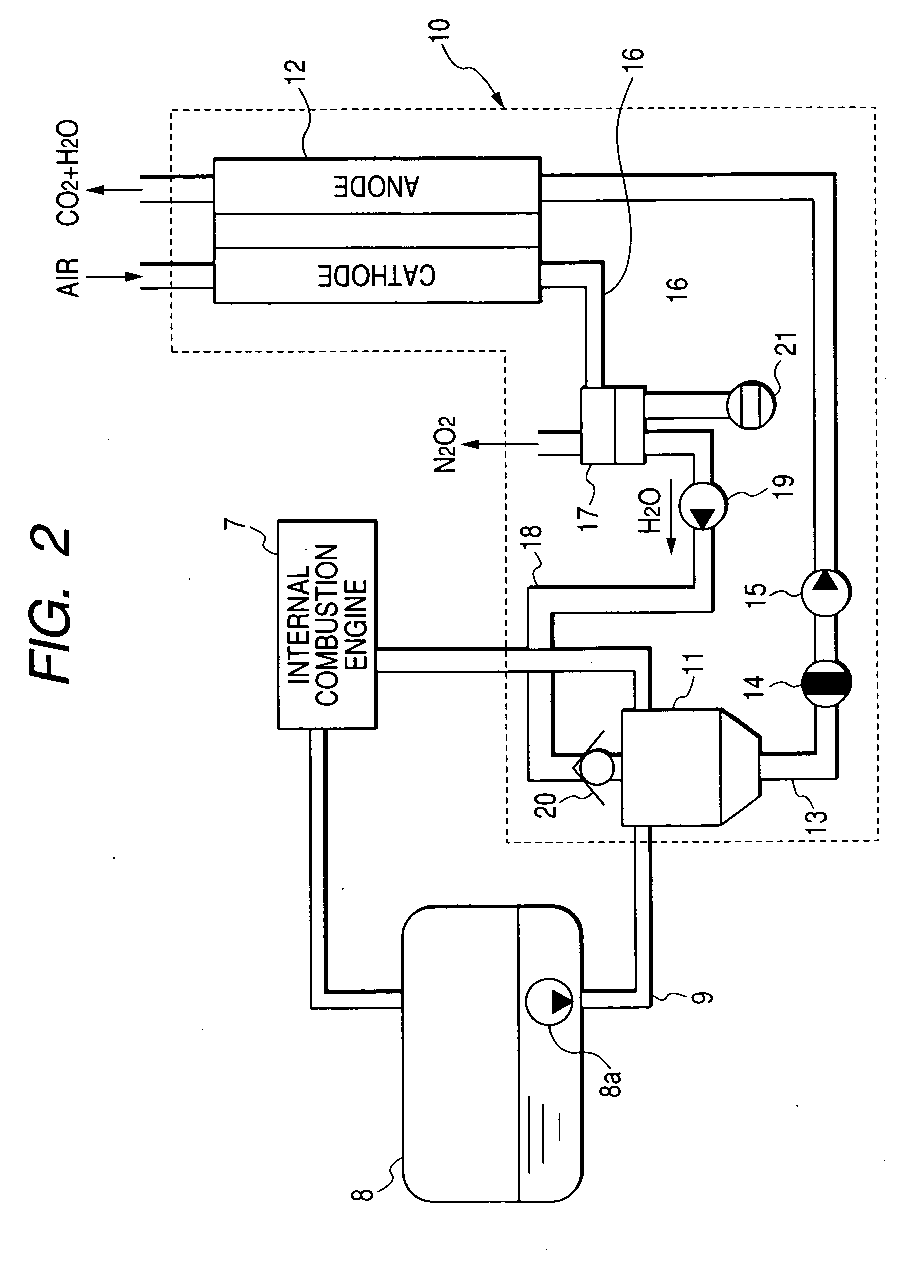
[0032]FIG. 1 is a schematic diagram mainly showing the entire configuration of the electric power generation system as a secondary battery charging system according to the first embodiment. FIG. 2 is a schematic diagram mainly showing an internal combustion engine 7, a fuel storage unit 8 for vehicle, and a fuel cell unit 10 that is installed in the electric power generation system shown in FIG. 1.

[0033] The vehicle is equipped with the electric power generation system of the first embodiment shown in FIG. 1 and the internal combustion engine 7 shown in FIG. 2 as a driving power source. The vehicle drives by the internal combustion engine 7. The internal combustion engine 7 is a gasoline engine or a diesel engine as a driving power source for vehicle. The secondary battery charging system as the electric power generation system has a...

second embodiment

[0083] Next, a description will now be given of the electric power generation system as the secondary battery charging system according to the second embodiment of the present invention.

[0084] The second embodiment shows another start-up condition that is different from the start-up condition performed in the first embodiment. Hereinafter, the different manner from the first embodiment will be explained.

[0085] The control circuit 31 in the control section 30 in the electric power generation system of the second embodiment detects a no-load voltage or open-circuit voltage of the secondary battery 1 and estimates the SOC (state of charge) of the secondary battery 1.

[0086] On halting the operation of the internal combustion engine 7, when the control circuit 31 detects that the SOC of the secondary battery 1 estimated from the open-circuit voltage of the secondary battery 1 is lower than a given voltage value, the control circuit 31 generates and outputs the start-up signal to the o...

third embodiment

[0088] Next, a description will now be given of the electric power generation system as the secondary battery charging system according to the third embodiment of the present invention with reference to FIG. 6.

[0089] Hereinafter, only the components and manner different from the first embodiment will be explained.

[0090]FIG. 6 is a sectional diagram showing the configuration of another fuel cell storage unit installed in the electric power generation system according to the third embodiment of the present invention. In FIG. 6, reference character 11g designates an ethanol selection permeable membrane for separating the ethanol from the ethanol mixed gasoline. In the second embodiment, the fuel storage unit 11 is equipped with the ethanol selection permeable membrane 11g placed at the boundary between the first body part 11a and the second body part 11b. The ethanol selection permeable membrane 11g penetrates only ethanol or ethanol and water, not gasoline. For example, a porous zeo...


PUM


Abstract

An electric power generation system is mounted on a vehicle having a secondary battery, an electric load, and an internal combustion engine as a driving source consuming gasoline in a mixed fuel which mainly consists of the gasoline and ethanol. The electric power generation system has a fuel cell for generating electric power by electric chemical reaction and a fuel storage unit having an ethanol selection permeable membrane for separating the ethanol from the mixed fuel involving the ethanol and gasoline. On satisfying a given condition, the fuel cell receives the ethanol from the permeable membrane and initiates the generation of electric power, and supplies the generated electric power at least one of the secondary battery and the electric load.

Description

CROSS-REFERENCE TO RELATED APPLICATIONS [0001] This application is related to and claims priority from Japanese Patent Application No. 2005-32069 filed on Feb. 8, 2005, the contents of which are hereby incorporated by reference. BACKGROUND OF THE INVENTION [0002] 1. Field of the Invention [0003] The present invention relates to an electric power generation system, to be mounted on a vehicle, equipped with a fuel cell capable of generating an electric power using fuel such as ethanol separated from mixed fuel for an internal combustion engine. [0004] 2. Description of the Related Art [0005] Recently, a growing number of auxiliary apparatus or devices mounted on a vehicle and of functions thereof has increased the amount of current power consumption or a dark current while the vehicle is in idle or stops. This introduces a possibility of discharging a battery installed in a vehicle. In general, a built-in battery of a vehicle self-discharges while an engine of the vehicle is stopped a...

Claims


Application Information

Patent Timeline
IPC IPC(8): B60K6/00B60K6/32B60K8/00H01M8/00H01M8/04H01M8/06H02P9/04
CPCB60K25/00Y02T90/34B60L58/30Y02T90/40Y10S903/908Y10S903/944
Inventor USAMI, HIROYUKIKIKUCHI, TETSUROKATO, AKIRAOSHIMA, HISAYOSHI
Owner DENSO CORP
Why Eureka
Try Eureka