

Linear hydraulic stepping actuator with fast close capabilities
a hydraulic actuator and linear technology, applied in the direction of fluid couplings, servomotors, wellbore/well accessories, etc., can solve the problems of inability to manually maintain the deep subsea wellhead assembly, inability to produce all wells at the same time, undesirable loss of production fluids, etc., to avoid mechanical locking mechanisms and eliminate excessive lines or solenoid valves.
- Summary
- Abstract
- Description
- Claims
- Application Information
AI Technical Summary
Benefits of technology
Problems solved by technology
Method used
Image

Examples
embodiment 1
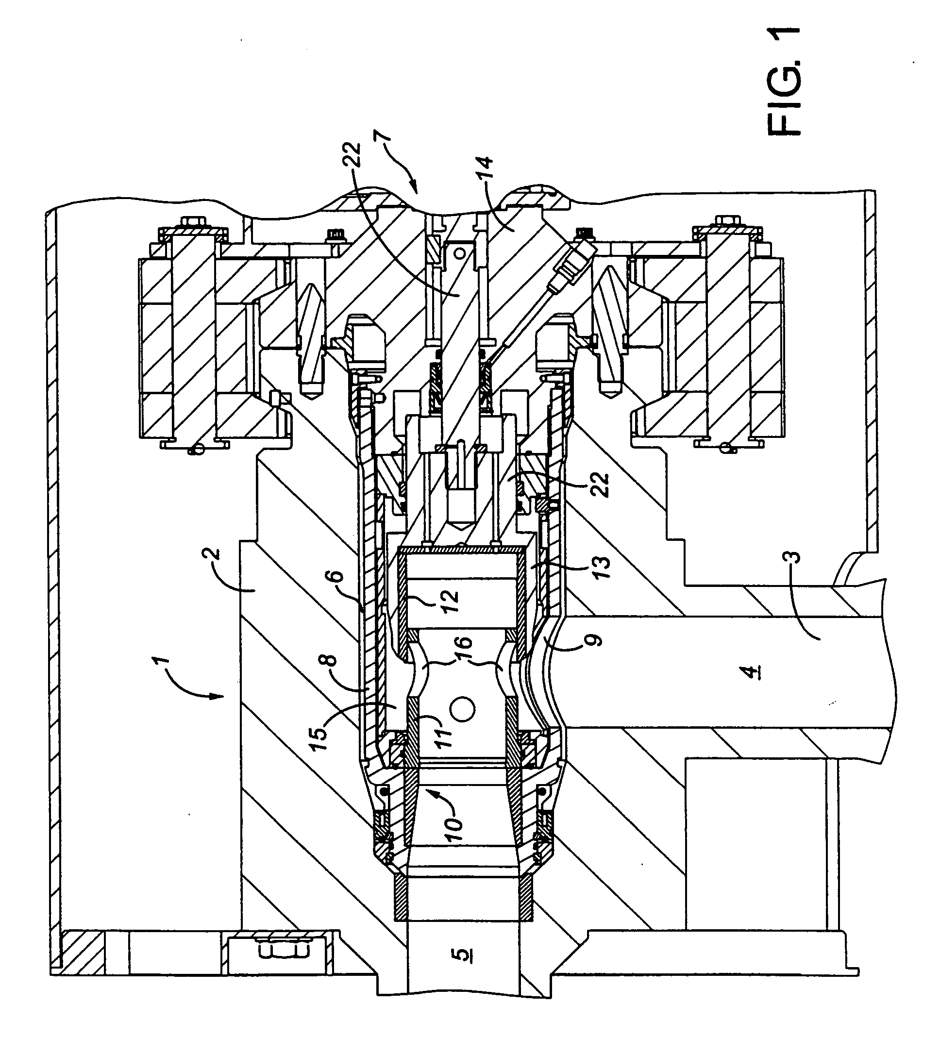
, FIG. 3
[0081] The closing force for the actuator 20 in this configuration is supplied by the spring 26 that acts on the top of the actuator piston 21. Fluid in the upper chamber 24 is used as a reservoir only for the opening slave cylinder 31. In order to activate the “fast close” mode in this configuration both solenoid valves 54 and 56 are energized. This allows reverse flow through the two pilot operated check valves 72, 74 to drain all fluid from the lower chamber 25 of the actuator cylinder 20, allowing the spring 26 to push the piston 21 and thus the choke valve to the full closed position.
[0082]FIG. 3 illustrates a hydraulic schematic that allows the communication between control module 76 and the actuator cylinder 20. The control module 76 functions as a fluid power distribution device located subsea that, through the use of solenoid operated control valves 54, 56, directs the fluid pressure as intended. All references to the solenoid operated control valves 54, 56 refers ...
embodiment 2
, FIG. 4
[0087] This embodiment adds a third solenoid operated control valve 82 (or other directional control valve) for directly activating the “fast close” feature with a single pilot operated check valve 72 in the fast close line 70, thereby eliminating pilot valve 74 from FIG. 3. The open and close stepping functions are otherwise the same as described for FIG. 3, with the upper chamber 24 of the actuator cylinder 20 being used only as a supply storage for the opening slave cylinder 31. When solenoid valve 82 is energized, pressurized fluid is allowed to travel through fast close control line 84 to release the pilot check valve 72. All references to the solenoid operated control valves in the following text will refer to operation of the control module 76 as these are contained within this apparatus.
Open Movement
[0088] Solenoid 54 is energized allowing pressurized fluid from the hydraulic supply 27 to move into the left chamber 38 of the opening slave cylinder 31. This pressur...
embodiment 3
, FIG. 5
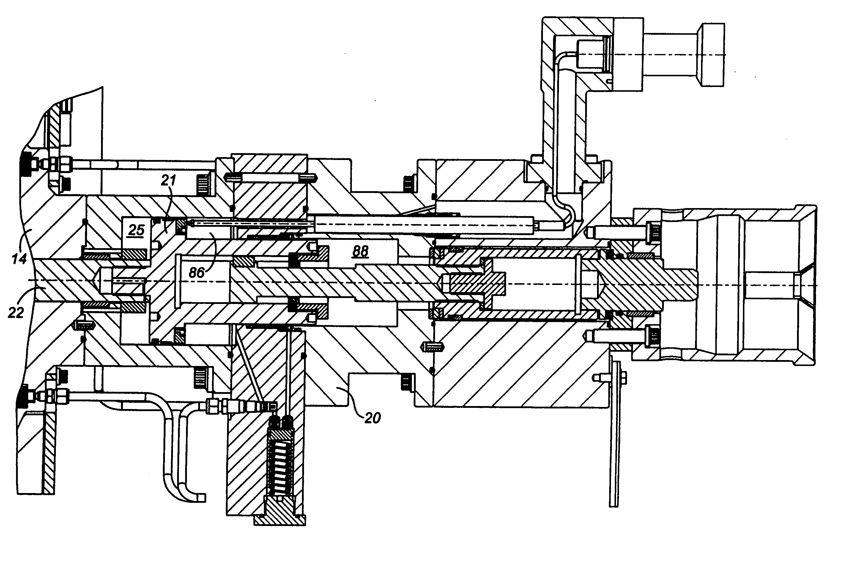
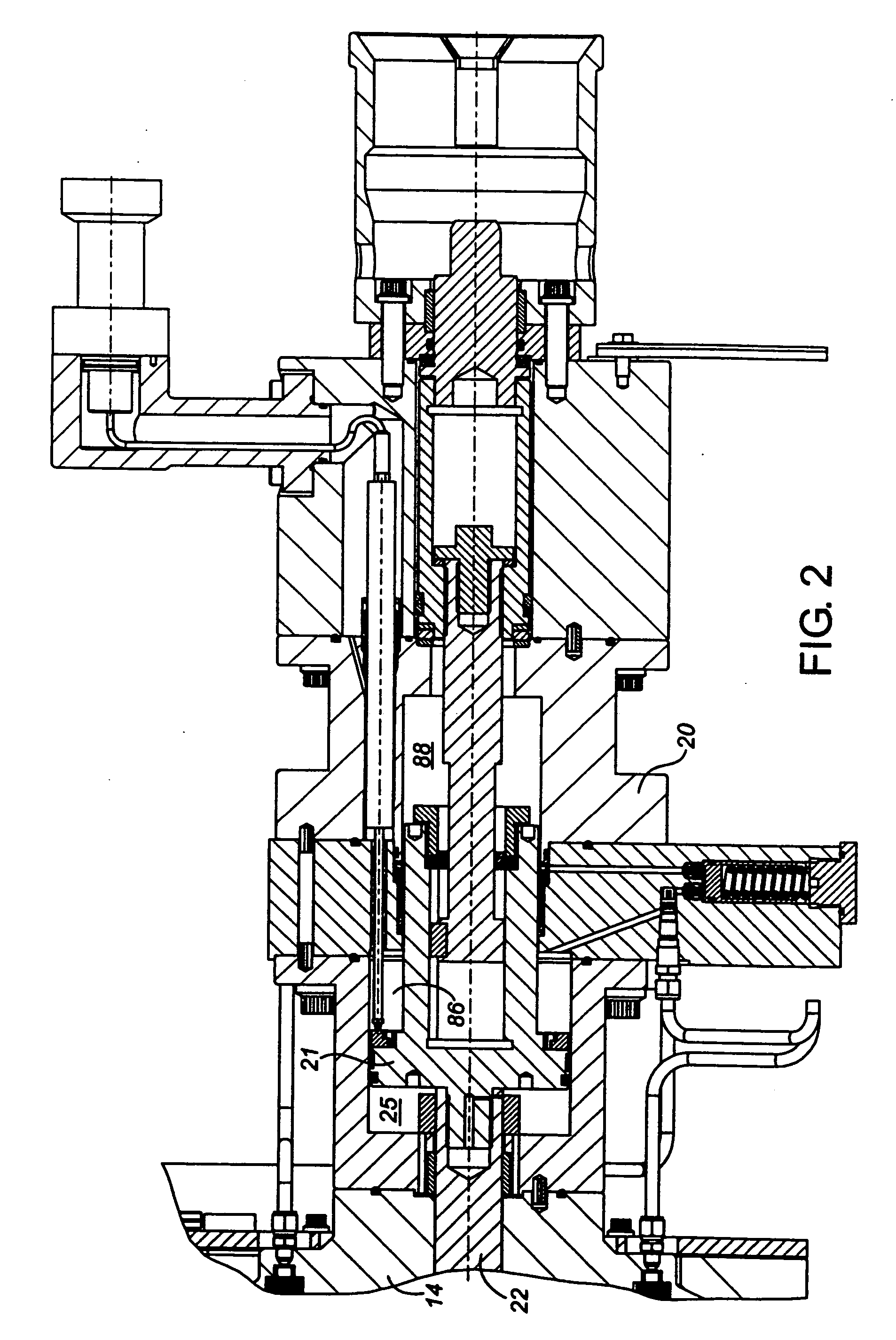
[0091] This embodiment varies considerably from the previous two embodiments in that it uses a dual acting hydraulic cylinder as the actuator 20, which in effect divides the upper chamber 24 of the previous embodiment into two chambers, a middle chamber 86 and an uppermost chamber 88. The uppermost chamber 88 is under supply pressure during all operational periods thus biasing the piston 21 in the closed direction. The open and closed stepping functions are otherwise similar to those of FIGS. 3 and 4.
[0092] The “fast close” mechanism for in this schematic is similar to that used in FIG. 4. When solenoid valve 82 is energized the pilot operated check valve 72 allows reverse flow and dumps all the pressure in the lower chamber 25 of the actuator cylinder 20 to middle chamber 86 which is at vent pressure. Uppermost chamber 88 is still pressurized to supply pressure and as such the actuator piston 21 moves to the full closed position.
[0093] This embodiment of the invention thu...
PUM
 Abstract
Description
Claims
Application Information