Battery pack
a battery pack and battery charger technology, applied in the field of batteries, can solve the problems of reducing the capacity of the battery set, affecting the service life of the battery pack, and the entire battery pack becoming unusable, so as to achieve the effect of only reducing the capacity
- Summary
- Abstract
- Description
- Claims
- Application Information
AI Technical Summary
Benefits of technology
Problems solved by technology
Method used
Image
Examples
first embodiment
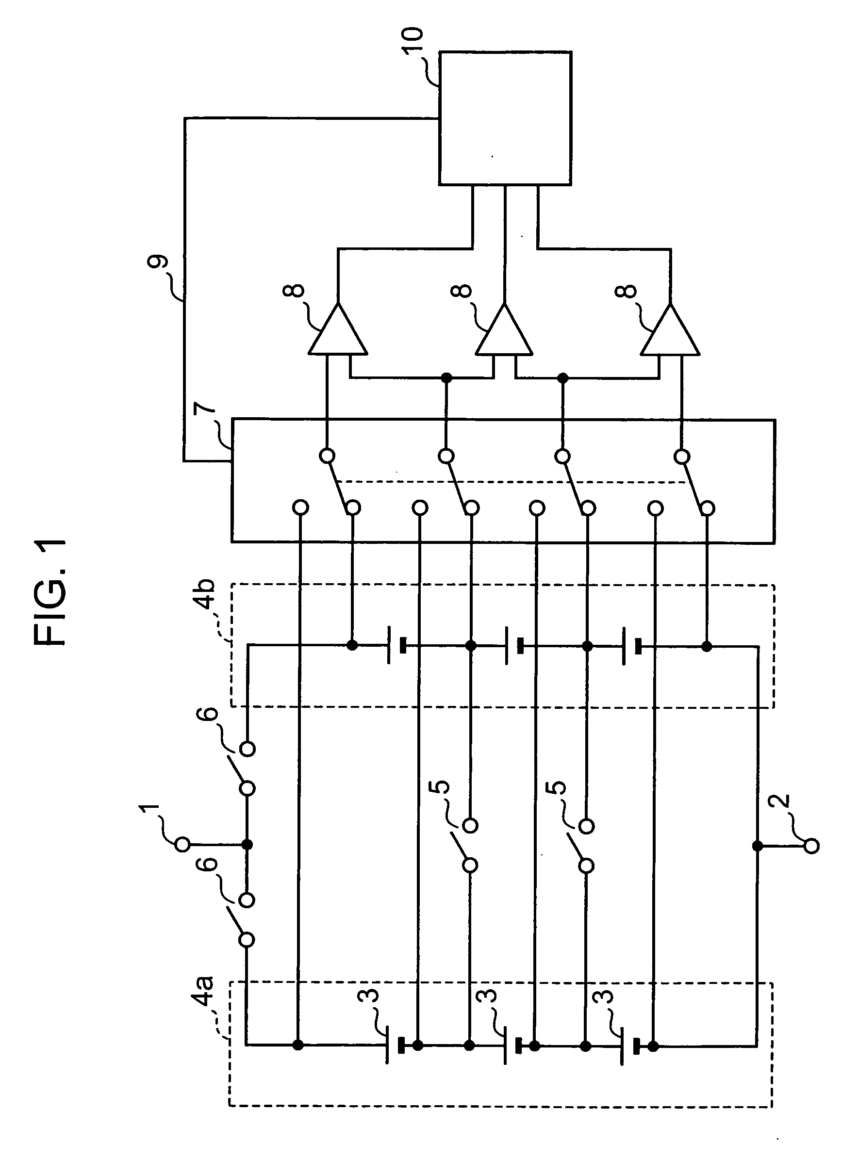
[0023]FIG. 1 is a circuit diagram, typifying the circuit configuration of a battery pack according to a first embodiment of the present invention. In this case, the number of series modules in parallel is two.
[0024] In FIG. 1, reference numeral 1 denotes a plus terminal and reference numeral 2 designates a minus terminal. The plus terminal 1 and the minus terminal 2 are connected to an external circuit (not shown) as the external load. Three secondary-battery cells 3 are connected in series to form each series module 4a, 4b. The two series modules 4a, 4b are connected in parallel between the plus terminal 1 and the minus terminal 2. Thereby, a battery set is formed.
[0025] In addition, the secondary-battery cells 3 which make up the series modules 4a, 4b are each connected in parallel via a parallel-connection separation switch 5. Besides, a battery-set circuit separation switch 6 is connected to each series module 4a, 4b. Thereby, each series module 4a, 4b can be separated from a ...
second embodiment
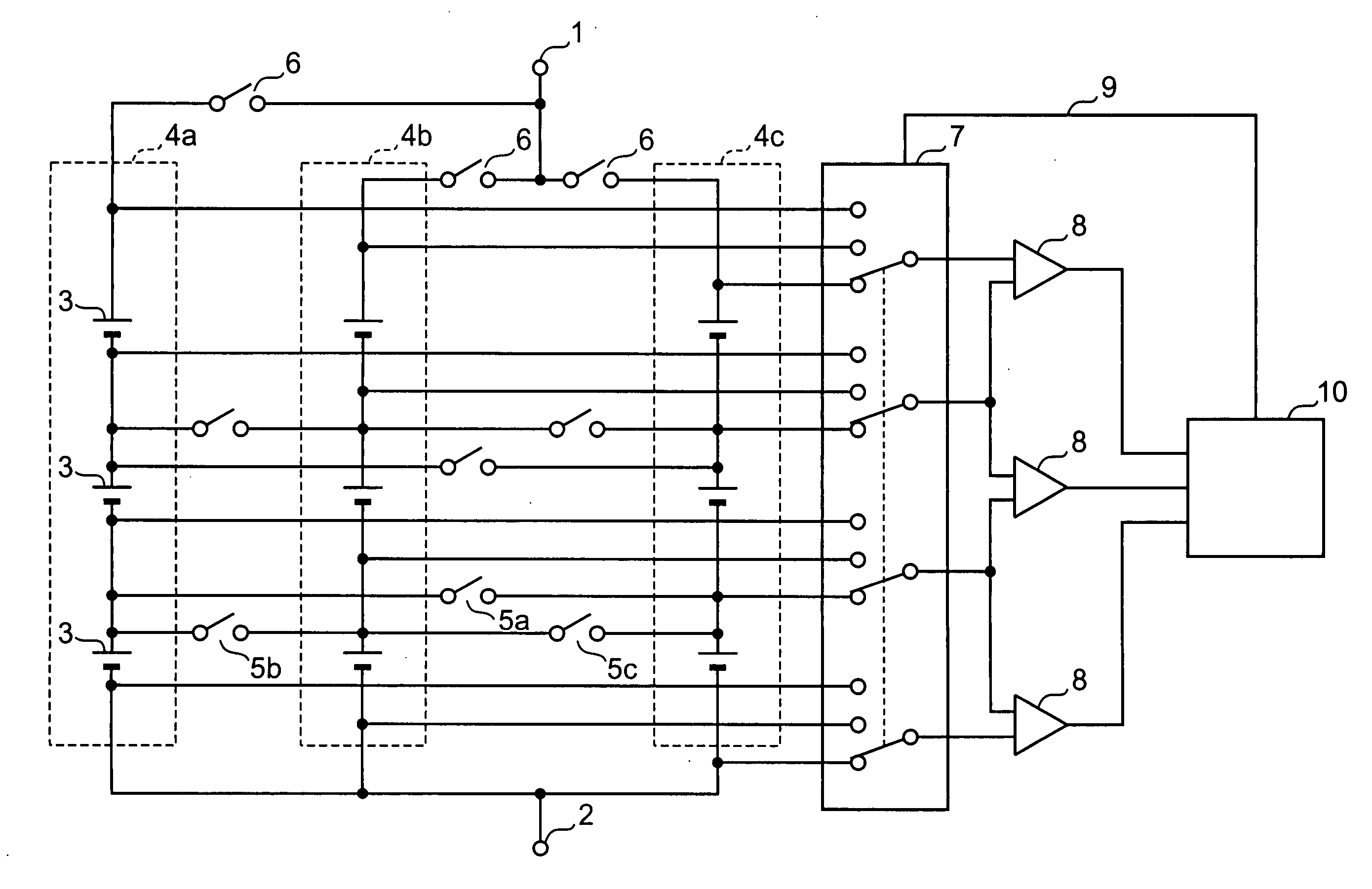
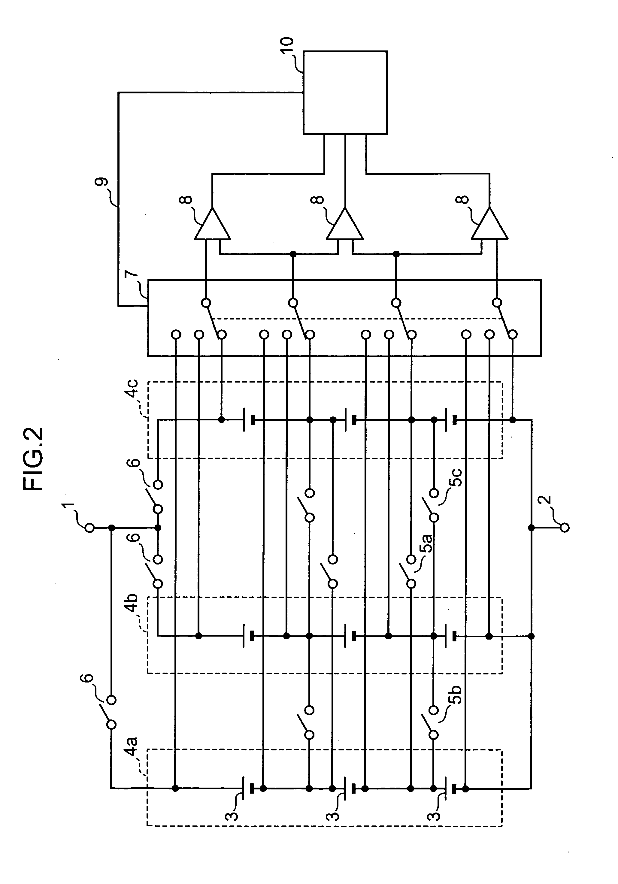
[0034]FIG. 2 is a circuit diagram, typifying the circuit configuration of a battery pack according to a second embodiment of the present invention. In this case, the number of series modules in parallel is three.
[0035] Herein, component elements are given the same reference characters and numerals as those of FIG. 1, as long as they each have an equivalent function to those according to the first embodiment described earlier. Thus, their description is omitted. The method of monitoring the voltage at the time of an ordinary operation and measuring the voltage of the individual secondary-battery cells 3 at regular intervals is identical to that of the first embodiment
[0036] This embodiment is different from the first embodiment, in the connection relation between three series modules 4a, 4b, 4c and three parallel-connection separation switches 5a, 5b, 5c. FIG. 3 is an illustration, typifying the connection relation between the series modules and the parallel-connection separation s...
third embodiment
[0039] As described so far, in the first embodiment or the second embodiment, individual secondary-battery cells are directly connected via parallel-connection separation switches. In this connection method, their circuit can be easily formed in the case of two or three series modules. However, if more series modules are provided, they are difficult to connect in a network form. Hence, according to a third embodiment of the present invention, this problem can be resolved in the following way.
[0040]FIG. 4 is a circuit diagram, typifying the circuit configuration of a battery pack according to the third embodiment. In this case as well, the number of series modules in parallel is three.
[0041] Herein, component elements are given the same reference characters and numerals as those of FIG. 1, as long as they each have an equivalent function to those according to the first embodiment described earlier. Thus, their description is omitted. The method of monitoring the voltage at the time...
PUM
 Abstract
Description
Claims
Application Information
 - R&D
- Intellectual Property
- Life Sciences
- Materials
- Tech Scout
- Unparalleled Data Quality
- Higher Quality Content
- 60% Fewer Hallucinations
Browse by: Latest US Patents, China's latest patents, Technical Efficacy Thesaurus, Application Domain, Technology Topic, Popular Technical Reports.
© 2025 PatSnap. All rights reserved.Legal|Privacy policy|Modern Slavery Act Transparency Statement|Sitemap|About US| Contact US: help@patsnap.com


