Drive recorder and control method therefor

a technology of drive recorder and control method, which is applied in the direction of instruments, anti-theft devices, and groovy, etc., can solve the problems of wasting electricity, shortening the life of flash memory, and affecting the accuracy of flash memory, so as to minimize wasted electricity, prolong the life of nonvolatile memory, and high accuracy

Inactive Publication Date: 2006-08-31
SANYO ELECTRIC CO LTD
View PDF7 Cites 75 Cited by
  • Summary
  • Abstract
  • Description
  • Claims
  • Application Information

AI Technical Summary

Benefits of technology

[0010] If the acceleration exceeds the threshold value, the drive recorder of the present invention performs sound recognition of sample sound data and transcribes image data into the nonvolatile memory only when the accident sound is determined to be included in the sound data. As such, in addition to determination on the basis of the acceleration, determination using sound recognition enables high accuracy determination of the occurrence / nonoccurrence of an accident and thus minimizes wasted electricity as well as extends the life of a nonvolatile memory compared to that of a conventional drive recorder. Further, writing data into a nonvolatile memory enables a write at once method drive recorder to be commercialized. Furthermore, high speed sound recognition with the use of a DSP or the like enables reliably storing image data into a nonvolatile memory, captured accurately at the occurrence time of an accident.
[0011] According to the present invention, a drive recorder and control method therefor with high accuracy in recognizing the occurrence / nonoccurrence of an accident is provided.

Problems solved by technology

Therefore, in a case the above threshold value is set permissively, improper operations frequently occur due to reasons besides accidents such as sudden braking or abrupt steering and sudden acceleration.
This generates unnecessary processes of transcribing data thus causing problems of wasting electricity as well as shortening the flash memory life.
As such, it was very difficult to set the above threshold value appropriately.

Method used


Image

  • Drive recorder and control method therefor
  • Drive recorder and control method therefor
  • Drive recorder and control method therefor

Examples


Embodiment Construction

[0018] At least the following matters will be made clear by the explanation in the present specification and the description of the accompanying drawings.

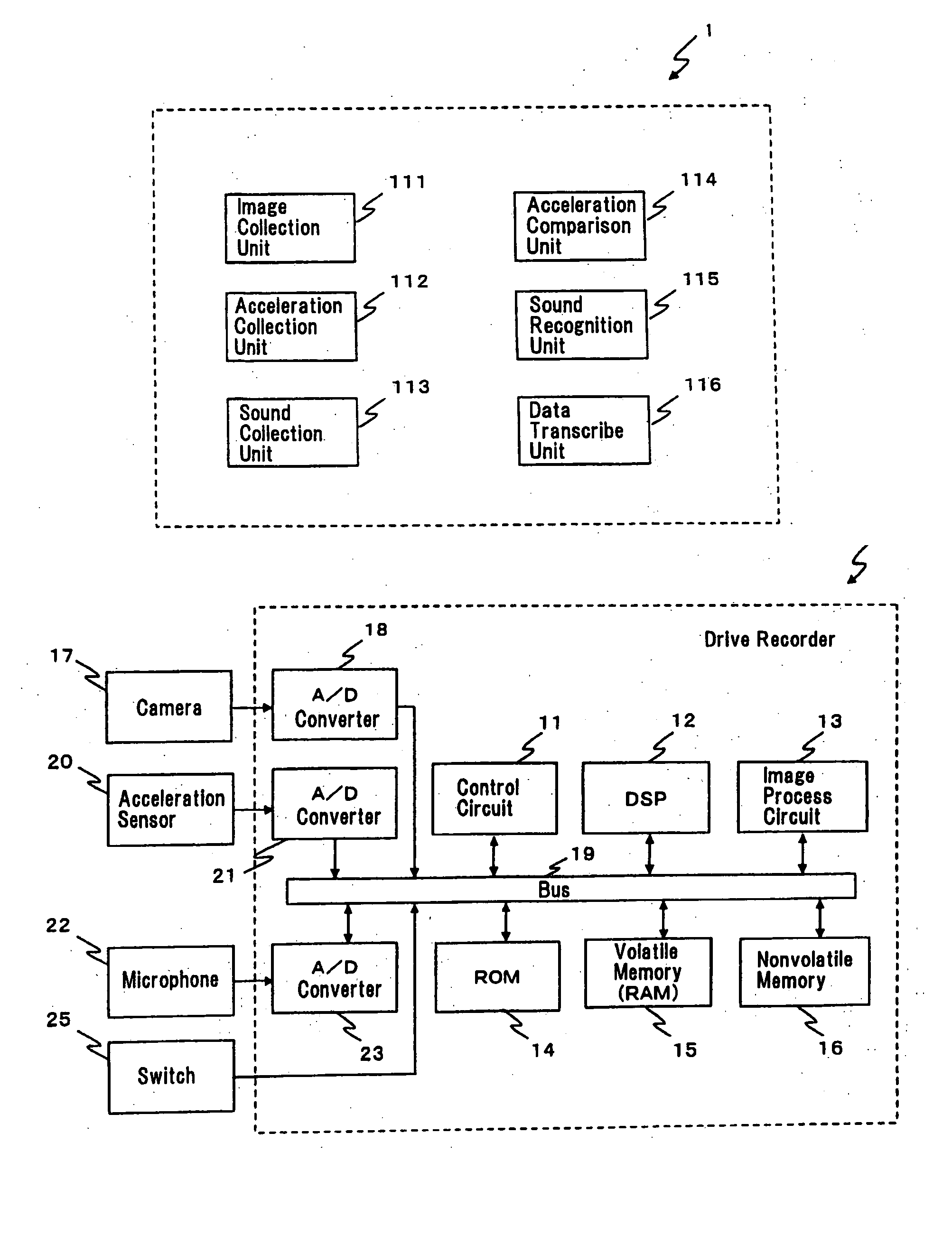
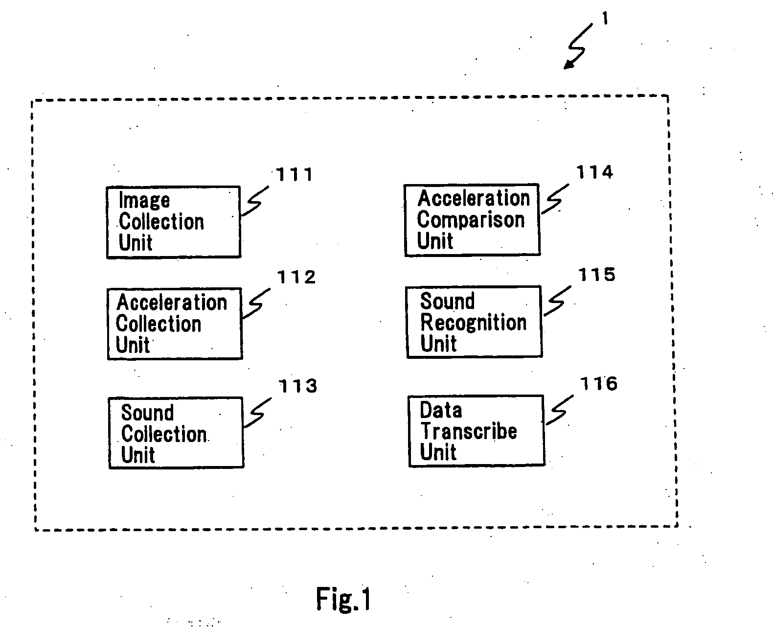
[0019] An implementation of the present invention will be described in detail below. FIG. 1 illustrates characteristic functions of a drive recorder 1 according to the implementation of the present invention. An image collection unit 111 of FIG. 1 stores in real-time into a first memory, image data representing images captured while the vehicle is in motion. An acceleration collection unit 112 measures the acceleration of the vehicle in motion. A sound collection unit 113 stores in real-time into the first memory, sound data representing sound captured while the vehicle is in motion. An acceleration comparison unit 114 compares in real-time acceleration with the threshold value and determines whether or not the acceleration exceeds the threshold value. When it is determined that the acceleration has exceeded the threshold value, a...


PUM


Abstract

A drive recorder 1 comprises a volatile memory 15, a nonvolatile memory 16, an image collection unit 111 that stores in real-time image data into the volatile memory 15, an acceleration collection unit 112, a sound collection unit 113 that stores in real-time sound data into the volatile memory 15, an acceleration comparison unit 114 that determines in real-time whether the acceleration exceeds a threshold value, a sound recognition unit 115 that determines if the sound data includes an accident sound which is a distinctive sound that is generated at an accident, by performing sound recognition on sound data when the acceleration exceeds the threshold value, and a data transcribe unit 116 that transcribes image data stored in the volatile memory 15 into the nonvolatile memory 16 when it is determined that the accident sound is included in the sound data.

Description

CROSS-REFERENCE TO RELATED APPLICATIONS [0001] The present application claims priority from Japanese Patent Application No. 2005-14615 filed on Jan. 21, 2005, which is herein incorporated by reference. BACKGROUND OF THE INVENTION [0002] 1. Field of the Invention [0003] The present invention relates to a drive recorder and control method therefor, and relates particularly to technology for realizing a drive recorder having high recognition accuracy On the occurrence / nonoccurrence of an accident. [0004] 2. Description of the Related Art [0005] Japanese Patent Application Laid-open Publication No. 2000-6854 discloses a drive recorder that can record the circumstances of a vehicle accident. That drive recorder has a function to store in real-time into the RAM (Random Access Memory) images taken by a CCD camera and information (hereinafter called ‘accident information’) collected by various sensors, and transcribes the above information into a nonvolatile memory such as a flash memory at...

Claims


Application Information

Patent Timeline
Patent Type & Authority Applications(United States)
IPC IPC(8): B60Q1/00H04N7/18B60R25/10G08B19/00G10L15/00G10L17/26
CPCB60R25/302B60R25/305G07C5/0891G07C5/0866B62D41/00G01D9/005G11B20/10
Inventor YAMAMURA, KAZUYA
Owner SANYO ELECTRIC CO LTD
Why Eureka
Try Eureka