
LED driver

a technology of led driver and driver body, which is applied in the direction of static indicating device, semiconductor lamp usage, instruments, etc., can solve the problems of lowering light efficiency, adversely affecting the stability of the circuit, generating unwanted electromagnetic interference (emi), and lowering light efficiency, so as to achieve the effect of improving light efficiency

Inactive Publication Date: 2006-08-31
SAMSUNG ELECTRONICS CO LTD
View PDF21 Cites 68 Cited by
  • Summary
  • Abstract
  • Description
  • Claims
  • Application Information

AI Technical Summary

Benefits of technology

[0020] Accordingly, it is an aspect of the present invention to provide an LED driver which drives an LED at a low voltage while improving light efficiency.

Problems solved by technology

However, because an inductor is used to reduce the ripple current, the switching frequency must be raised or the inductor must have a large inductance.
As the inductance is raised, the transient phenomenon becomes slow, thereby lowering the light efficiency.
However, a reverse recovery current is generated in the second diode 284 while changing the divergence switch, which may adversely affect the stability of the circuit and generate unwanted electromagnetic interference (EMI).
Also, the DMD module is turned off until the reverse recovery current disappears and the circuit is stabilized, thereby lowering the light efficiency.
However, in order to adequately raise the charging slope, the power voltage Vcc may be too large.
However, as the power voltage becomes large, accordingly a switching noise and the EMI becomes large and components having a of the ability to withstand the higher voltage are needed, thereby raising the production costs.

Method used


Image

  • LED driver
  • LED driver
  • LED driver

Examples


Embodiment Construction

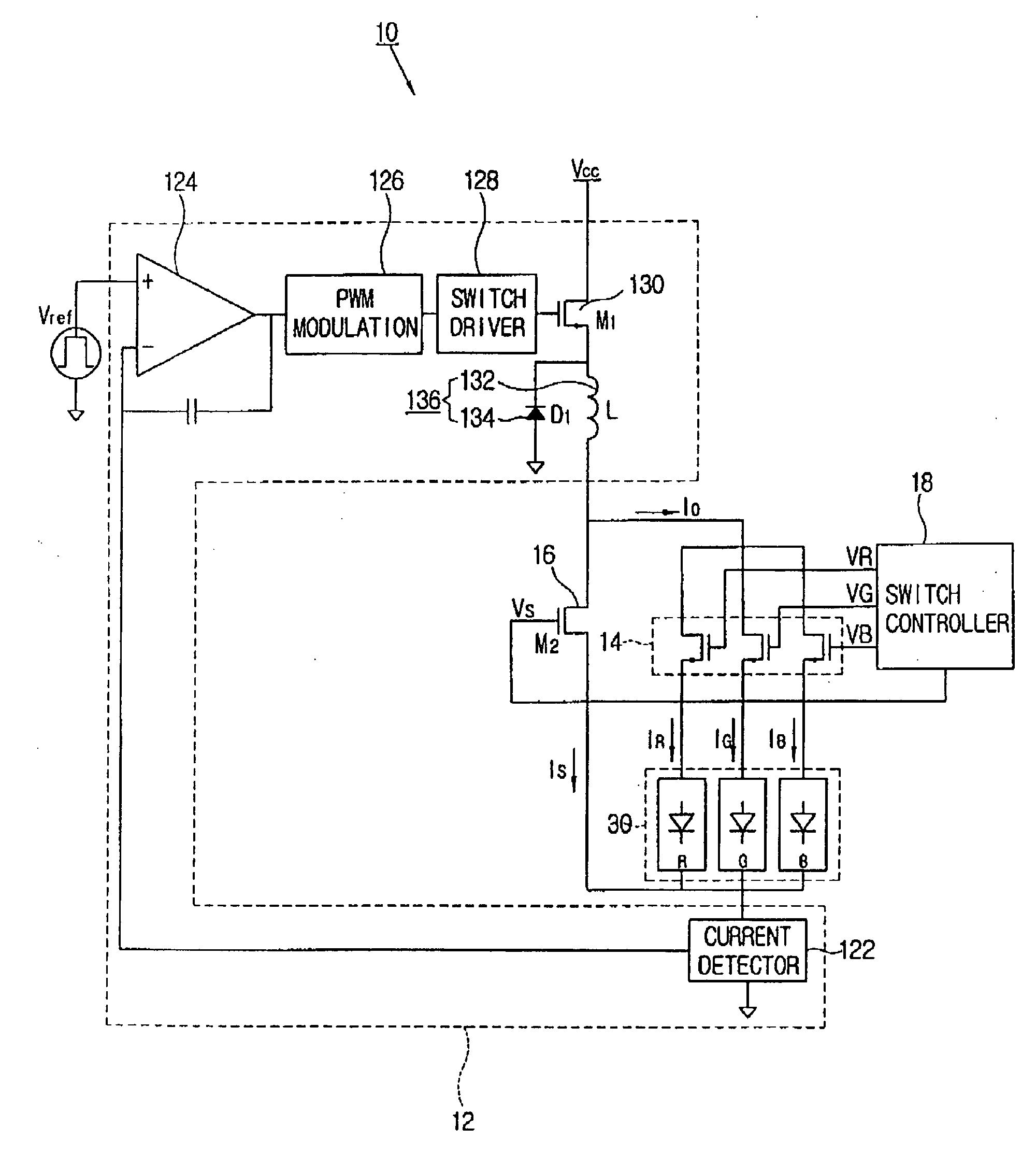
[0036] Reference will now be made in detail to exemplary embodiments of the present invention, which are illustrated in the accompanying drawings. The exemplary embodiments described below are not intended to be limiting, but rather are provided for a better understanding of the present invention. FIG. 4 illustrates a configuration of an LED driver 10 according to an embodiment of the present invention.

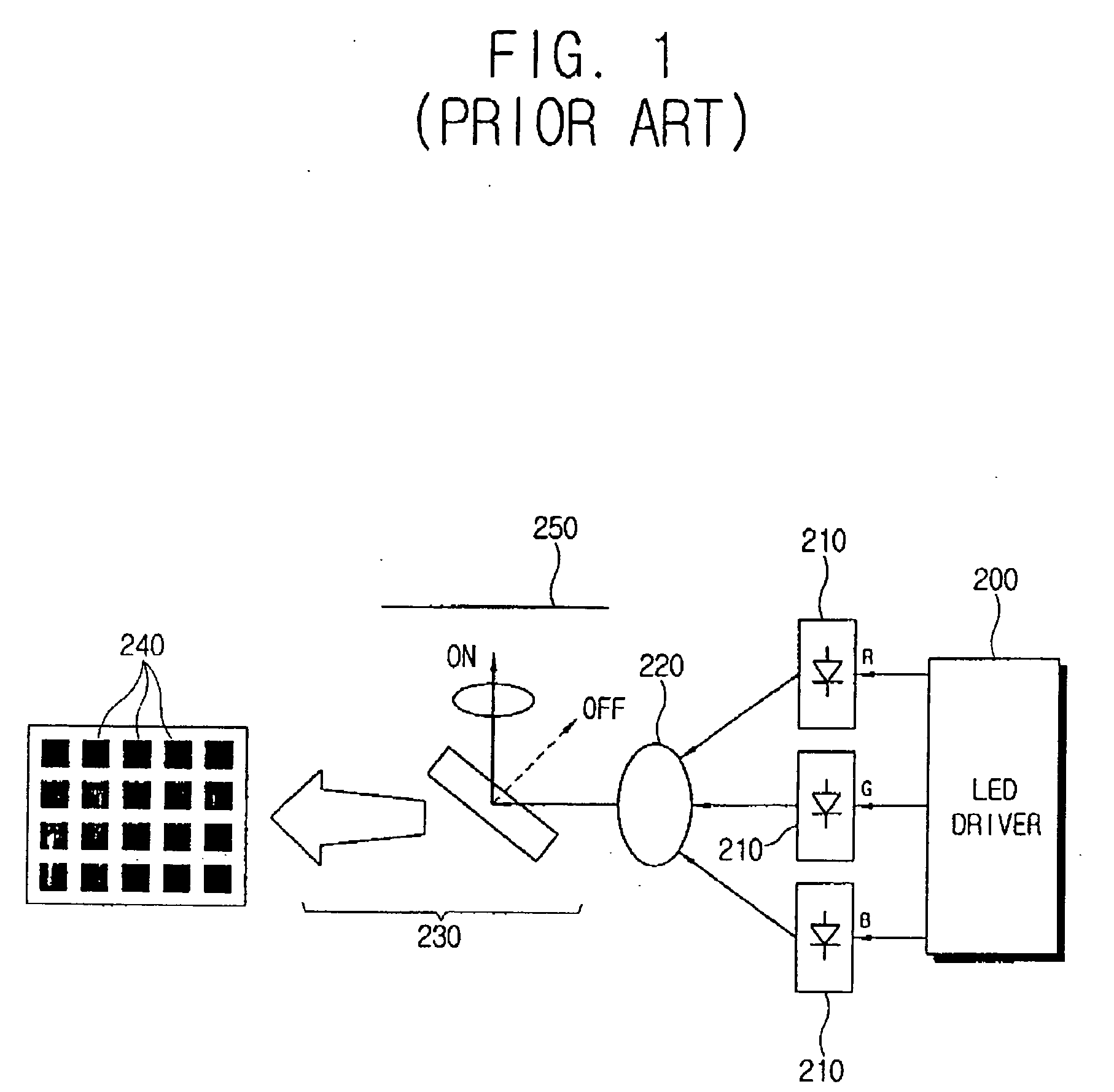
[0037] The LED driver 10 drives a plurality of LEDs 30 which are used as a light source of a digital micromirror device (DMD) display apparatus such as a digital light processing (DLP) projection TV, a projector, or the like using the DMD, and an LCD back light.

[0038] As shown in FIG. 4, the LED driver 10 comprises a current controller 12, a plurality of divergence switches 14, a bypass switch 16 and a switch controller 18. The plurality of divergence switches are disposed between the current controller 12 and anodes of the plurality of LEDs 30. Cathodes of the plurality of LEDs 30 ...


PUM


Abstract

The present invention relates to an LED driver for driving a plurality of light emitting diodes (LEDs), comprising a current controller to control power supply of a predetermined power source unit to make a current flowing in the plurality of LEDs reach a predetermined target current value which sequentially changes corresponding to the respective LEDs; a plurality of divergence switches to flow or interrupt the current with respect to each of the plurality of LEDs; a bypass switch being connected in parallel with respect to the plurality of divergence switches and the plurality of LEDs and to flow or bypass the current supplied to the plurality of LEDs by being open or short-circuited; and a switch controller to sequentially open and close the plurality of divergence switches corresponding to change of the target current value and control the bypass switch to be short-circuited in a range where the current supplied to the LEDs increases, corresponding to the rise of the target current value. Thus, the present invention provides an LED driver which drives an LED in a low voltage to improve light efficiency.

Description

CROSS-REFERENCE TO RELATED APPLICATIONS [0001] This application claims the benefit under 35 U.S.C. §119(a) of Korean Patent Application No. 2005-0016209, filed on Feb. 26, 2005, in the Korean Intellectual Property Office, the disclosure of which is incorporated herein by reference. BACKGROUND OF THE INVENTION [0002] 1. Field of the Invention [0003] The present invention relates to an LED driver. More particularly, the present invention relates to an LED driver, which drives light emitting diodes at low power to improve efficiency. [0004] 2. Description of the Related Art [0005] Light emitting diodes (LEDs) are used as a light source of a liquid crystal display (LCD) apparatus, as well as a digital micromirror device (DMD) display apparatus such as a digital light processing (DLP) projection TV, a projector, and the like, using a DMD. [0006]FIG. 1 illustrates the DMD display apparatus which employs LEDs as the light source. The DMD display apparatus employs a plurality of LED modules...

Claims


Application Information

Patent Timeline
Patent Type & Authority Applications(United States)
IPC IPC(8): G09G3/14H05B44/00
CPCG09G3/3413G09G2320/064H04N9/3114H04N9/3155H04N9/3197H05B33/0815H05B33/0818H05B33/086Y02B20/347H05B45/20H05B45/375G09G3/32G09G3/34Y02B20/30H05B45/3725
Inventor KIM, NAM-IN
Owner SAMSUNG ELECTRONICS CO LTD
Features
  • Generate Ideas
  • Intellectual Property
  • Life Sciences
  • Materials
  • Tech Scout
  • Unparalleled Data Quality
  • Higher Quality Content
  • 60% Fewer Hallucinations
Learn More