Phase difference film and production method therefor

a technology of phase difference film and production method, which is applied in the direction of instruments, polarising elements, non-linear optics, etc., can solve the problems of increased production cost, easy corrosion, and increased materials and processes, and achieve the effect of low cost production

Inactive Publication Date: 2006-08-31
NITTO DENKO CORP
View PDF7 Cites 249 Cited by
  • Summary
  • Abstract
  • Description
  • Claims
  • Application Information

AI Technical Summary

Benefits of technology

[0015] Therefore, an object of the present invention is to provide a retardation film that has an optical retardation layer...

Problems solved by technology

For this reason, more materials and more processes are required, and the production cost will be raised.
Furthermore, since the optically anisotropic layer is composed of a polymer compound, it can be corroded easily by an organic solvent or the like contained in the liquid used for formation of the alignment film.
As a result, even when a liquid for formation of an alignment film is applied, the liquid may penetrate into the optically anisotropic layer, and lose its functions for the alignment films.
However, a step of coating a liquid crystalline compound on an alignment substrate and a step of transferring are required every time an optical retardation layer is formed in this method, and thu...

Method used


Image

  • Phase difference film and production method therefor
  • Phase difference film and production method therefor
  • Phase difference film and production method therefor

Examples


example 1

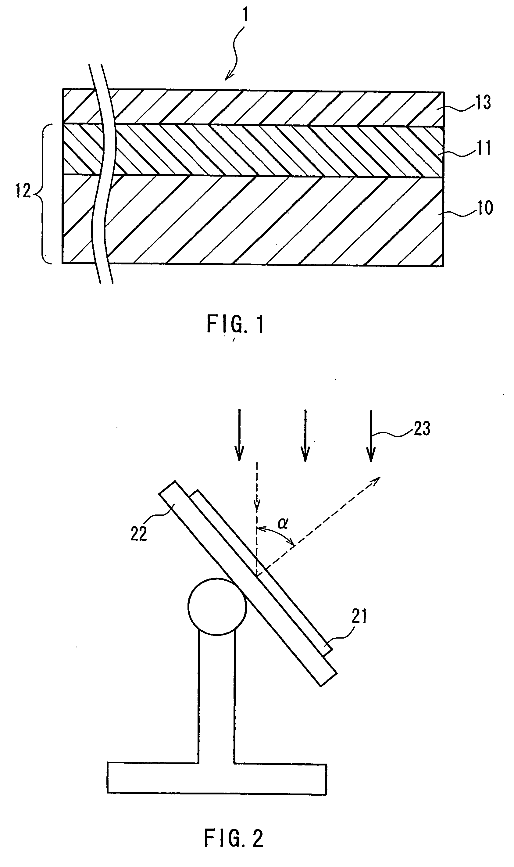
[0148]FIG. 1 shows a cross-sectional view of a retardation film produced in this Example. As shown in this figure, the retardation film 1 includes a transparent base 10, an optically anisotropic layer 11 and an optical retardation layer 13 laminated in this order, and the transparent base 10 and the optically anisotropic layer 11 form a base-attached anisotropic layer 12.

[0149] The retardation film 1 was produced in the following manner. First, a triacetylcellulose (TAC) base about 80 μm in thickness was prepared to make the transparent base 10.

[0150] Next, the base-attached anisotropic layer 12 was produced. Specifically, a 15 wt % solution of polyimide was prepared first. The polyimide in use was a copolymer of 2,2-bis(3,4-dicarboxyphenyl) hexafluoropropane (6FDA) and 2,2′-bis(trifluoromethyl)-4,4′-diaminobiphenyl (PFMB), and methyl isobutyl ketone (MIBK) was used for a solvent. This polyimide solution was applied onto the transparent base 10 and dried with heat at 130° C. for 1...

example 2

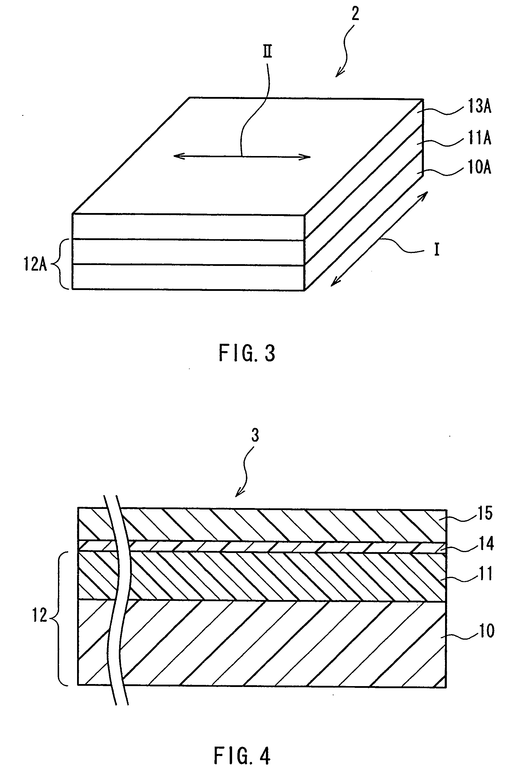
[0154]FIG. 3 is a perspective view of a retardation film produced in this Example. As shown in this figure, this retardation film 2 includes a base-attached optically anisotropic layer 12A containing a transparent base 10A and an optically anisotropic layer 11A, and an optical retardation layer 13A. In the figure, an arrow I denotes a stretch axis direction of the base-attached optically anisotropic layer 12A, and an arrow II denotes a polarization axis direction of the polarized ultraviolet light irradiated on the optical retardation layer 13A, and the both directions cross each other at right angles.

[0155] This retardation film 2 was produced in the following manner. First, a base-attached optically anisotropic layer was produced in the same manner as in Example 1, and was stretched by 10% its original length by a free-end uniaxial stretching at 150° C. in order to provide a base-attached optically anisotropic layer 12A having both the positive A-plate component and the C-plate c...


PUM

PropertyMeasurementUnit
Thicknessaaaaaaaaaa
Transparencyaaaaaaaaaa
Anisotropyaaaaaaaaaa

Abstract

A retardation film that has an optical retardation layer whose alignment direction is controlled precisely and that is produced at a low cost, and also a method for producing the same, are provided. The explanation below relates to FIG. 1. First, a base-attached anisotropic layer 12 is prepared by laminating an optically anisotropic layer 11 on a transparent base 10. Next, on the optically anisotropic layer 11, a solution containing a polymer reacting with polarized ultraviolet light and a liquid crystalline compound is coated and dried. Then, it is irradiated with polarized ultraviolet light so as to align the liquid crystalline compound, and irradiated further with unpolarized ultraviolet light as required to crosslink the liquid crystalline compound, thereby forming a retardation film 1 having an optical retardation layer 13 that is directly formed on the optically anisotropic layer 11.

Description

TECHNICAL FIELD [0001] The present invention relates to a retardation film that is used preferably for an image display apparatus such as a liquid crystal display (LCD) or the like, and a method for producing the same. BACKGROUND ART [0002] A retardation film (called also an optically compensation film, a compensation sheet and the like) is an important member for realizing an improvement in contrast and enlargement of a viewing angle range by means of an optical compensation in an image display apparatus such as a liquid crystal display. [0003] Recently, in an optical compensation using the retardation film, for further improved compensation, techniques of laminating plural layers having optical axes directions that are different from each other have been proposed often. For example, it is reported that for particularly compensating a viewing angle of a LCD used for an airplane part, use of an A-plate retardation film and an O-plate retardation film in a superimposed state is effec...

Claims


Application Information

Patent Timeline
IPC IPC(8): G02F1/1335B29C65/52B29L9/00G02B5/30G02F1/13363H01L51/50H05B33/02
CPCG02B5/3016G02B5/30G02F1/13363
Inventor SHUTOU, SHUNSUKEKOBAYASHI, HIROAKIMATSUNAGA, TAKUYA
Owner NITTO DENKO CORP
Why Eureka
Try Eureka