Device, system, and method for aiding valve annuloplasty

a technology of annuloplasty and device, applied in the field of medical devices, can solve the problems of reduced ejection reduced stroke volume of the left ventricle, and reduced valve proper function, and achieve the effect of improving apposition

Active Publication Date: 2006-08-31
MEDTRONIC VASCULAR INC
View PDF8 Cites 544 Cited by
  • Summary
  • Abstract
  • Description
  • Claims
  • Application Information

AI Technical Summary

Benefits of technology

[0010] The reference ring may include an inflatable portion that can be temporarily expanded on the inferior side of the valve annulus. The expanded portion of the reference ring deforms the valve annulus into a temporary ledge or shelf for improved apposition with an annuloplasty ring. Thus, the reference ring may provide a non-optical imaging aid for locating the valve annulus, and / or a physical aid for correctly positioning an annuloplasty ring with respect to the valve annulus.

Problems solved by technology

Heart valves, such as the mitral and tricuspid valves, are sometimes damaged by diseases or by aging, which can cause problems with the proper function of the valve.
This results in reduced ejection volume from the left ventricle, causing the left ventricle to compensate with a larger stroke volume.
The increased workload eventually results in dilation and hypertrophy of the left ventricle, further enlarging and distorting the shape of the mitral valve.
If left untreated, the condition may result in cardiac insufficiency, ventricular failure, and death.
Non-optical visualization of the valve annulus is challenging.
Under fluoroscopy, the cardiac tissues do not appear, making it very difficult to accurately align the annuloplasty ring prior to its implantation.
However, when treating the mitral valve, repeated injections of contrast dye are not practical because of rapid wash-out in high-flow area being treated.
Additionally, to make the high-volume contrast injections, the annuloplasty catheter system would require more lumens, larger lumens, or an additional catheter, none of which is desirable during catheterization procedures.
Furthermore, multiple high-volume contrast injections are not desirable for the patient due to potential complications in the renal system, where the radiopaque contrast medium is filtered from the blood.
However, none of the above techniques, used alone or in combination provides adequate visualization and guidance during catheter-based valve repair procedures.
Annuloplasty procedures are further challenged by the structure of the valve annulus.
In particular, the mitral valve annulus lacks a definable shelf or ledge for conveniently locating an annuloplasty ring.
However, during diastole, the mitral valve leaflets open towards the ventricular walls such that, in many cases, the valve annulus is not well defined.
Without the direct optical visualization that is provided during surgery, it is difficult to position an annuloplasty ring in abutment with the superior surface of the valve annulus.
Affixing the annuloplasty ring in such a misaligned position could have negative consequences for the patient, such as increasing mitral regurgitation and / or triggering ectopic heart beats.

Method used


Image

  • Device, system, and method for aiding valve annuloplasty
  • Device, system, and method for aiding valve annuloplasty
  • Device, system, and method for aiding valve annuloplasty

Examples


Embodiment Construction

[0021] One aspect of the present invention is a device having a non-optically visualizable reference ring for aiding in placement of an annuloplasty ring in abutment with a heart valve annulus. A visualization reference ring is designed to be temporarily positioned using intravascular catheterization techniques. Alternatively, surgical or minimally invasive, i.e. endoscopic techniques may be used to place the reference ring.

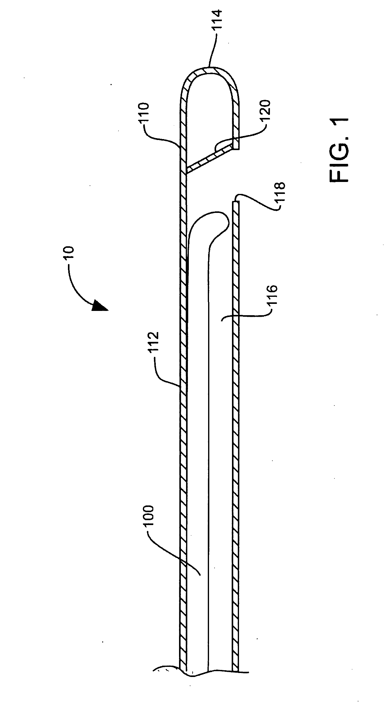
[0022]FIG. 1 illustrates system 10 for aiding in non-optical visualization of a valve annulus during an annuloplasty procedure. System 10 includes delivery catheter 110 having lumen 116 for delivering non-optical visualization reference ring 100 there through. Reference ring 100 is pre-formed in a distal portion of an elongate shaft, the entire shaft being slidable within and optionally removable from lumen 116. Delivery catheter 110 includes catheter body 112 shown with rounded distal tip 114. Delivery catheter 110 may have a straight tip or a preformed or defl...


PUM


Abstract

A device comprising a reference ring that may be temporarily disposed in abutment with the inferior perimeter surface of a heart valve to aid non-optical visualization of the valve annulus. The reference ring is elastically transformable between a straight delivery configuration and a generally circular or helical deployment configuration. The reference ring may include an inflatable portion that can be temporarily expanded on the inferior side of the valve annulus to deform the valve annulus into a temporary ledge or shelf for apposition with an annuloplasty ring. A system comprising a delivery catheter including a lumen with an exit port, the reference ring being slidably positionable within the lumen and being extendable from the exit port.

Description

TECHNICAL FIELD [0001] This invention relates generally to medical devices and particularly to a device, system, and method for aiding implantation of a heart valve annuloplasty ring. BACKGROUND OF THE INVENTION [0002] Heart valves, such as the mitral and tricuspid valves, are sometimes damaged by diseases or by aging, which can cause problems with the proper function of the valve. The mitral and tricuspid valves consist of leaflets attached to a fibrous ring or annulus. In a healthy heart, the mitral valve leaflets overlap during contraction of the left ventricle, or systole, and prevent blood from flowing back into the left atrium. However, due to various cardiac diseases, the mitral valve annulus may become distended, causing the leaflets to remain partially open during ventricular contraction and thus allowing regurgitation of blood into the left atrium. This results in reduced ejection volume from the left ventricle, causing the left ventricle to compensate with a larger stroke...

Claims


Application Information

Patent Timeline
Patent Type & Authority Applications(United States)
IPC IPC(8): A61M29/00
CPCA61B19/54A61B2019/5454A61F2/2445A61F2/2466A61F2250/0059A61F2250/0097A61F2230/0091A61B90/39A61B2090/3954
Inventor CRITTENDEN, JAMES F.
Owner MEDTRONIC VASCULAR INC
Why Eureka
Try Eureka