

Stator, motor, and method of manufacturing such stator
a technology of stator and motor, which is applied in the direction of dynamo-electric components, windings, magnetic circuit shapes/forms/construction, etc., can solve the problems of cumbersome work for winding the coils of each phase, complicated control of the claw pole motor, and cumbersome work for forming the stator, etc., to achieve easy formation, simplified manufacturing process of the stator, and enhanced manufacturing efficiency
- Summary
- Abstract
- Description
- Claims
- Application Information
AI Technical Summary
Benefits of technology
Problems solved by technology
Method used
Image

Examples
first embodiment
[0188] A first embodiment of the stator of the present invention will be explained below with reference to the accompanying drawings.
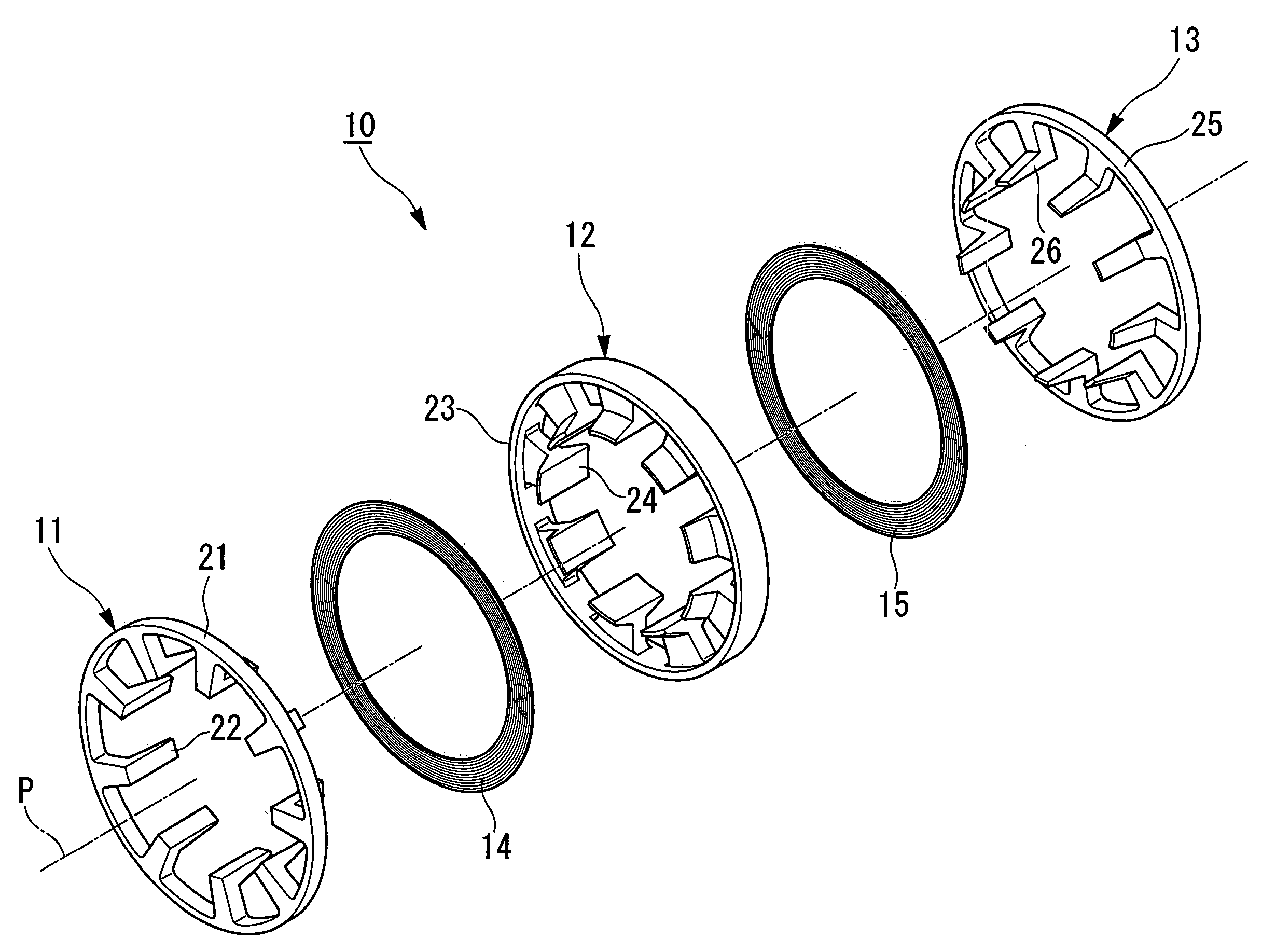
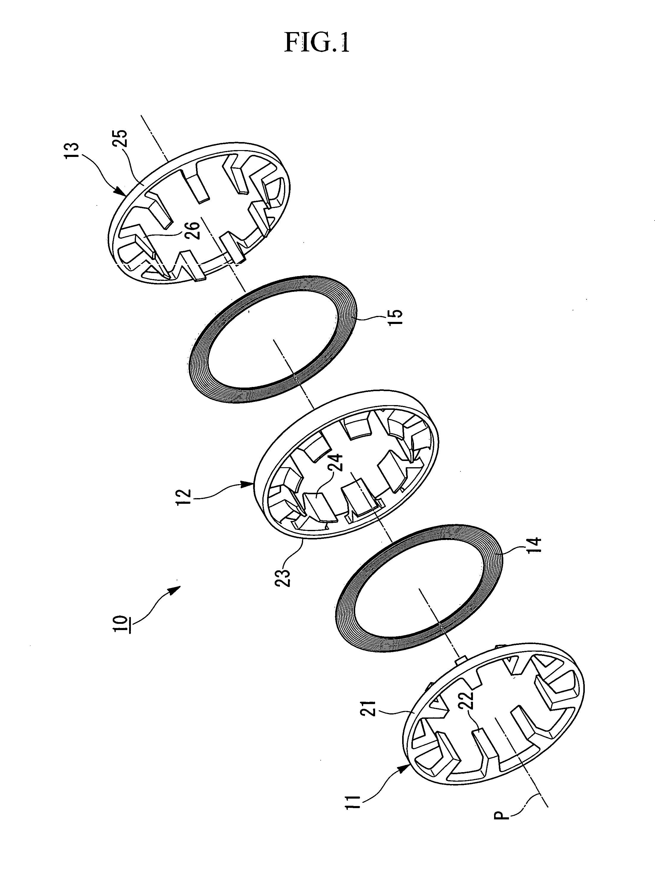
[0189] A stator 10 according to the present embodiment is a constituent element of a claw pole motor mounted, for example, in a hybrid vehicle as a driving source of the vehicle together with an internal combustion engine. For example, in a parallel hybrid vehicle of a structure in which the internal combustion engine, the claw pole motor, and a gear transmission are linked in series, a driving power of at least either the internal combustion engine or the claw pole motor is transmitted to driving wheels of the vehicle through the gear transmission.
[0190] When the driving power is transmitted to the claw pole motor from the driving wheels during deceleration of the vehicle, the claw pole motor serves as a generator that generates so-called regenerative-braking force and recover the kinetic energy of the vehicle in the form of electrical energy (regen...
second embodiment
[0221] A second embodiment of a stator of the present invention will be explained below with reference to the accompanying drawings.
[0222] A stator 110 according to the present embodiment is, similarly to the first embodiment, a constituent element of a claw pole motor mounted, for example, in a hybrid vehicle as a driving source of the vehicle together with an internal combustion engine. For example, in a parallel hybrid vehicle of a structure in which the internal combustion engine, the claw pole motor, and a gear transmission are linked in series, a driving power of at least either the internal combustion engine or the claw pole motor is transmitted to driving wheels of the vehicle through the gear transmission.
[0223] When the driving power is transmitted to the claw pole motor from the driving wheels during deceleration of the vehicle, the claw pole motor serves as a generator that generates so-called regenerative-braking force and recover the kinetic energy of the vehicle in ...
third embodiment
[0285] A third embodiment of the stator of the present invention will be explained below with reference to the accompanying drawings.
[0286] In a stator 50 according to the third embodiment, a point differing from the stator 110 according to the aforementioned second embodiment is that of a U-phase annular coil 54 and a W-phase annular coil 55 not having U-phase meandering portions 131 and W-phase meandering portions 132, respectively.
[0287] In the following, descriptions are omitted for those elements which are identical to those of the second embodiment.
[0288] The stator 50 according to the present embodiment, as shown, for example, in FIGS. 24 and 25, has U-phase stator ring 51 for the U-phase, V-phase stator ring 52 for the V-phase, and W-phase stator ring 53 for the W-phase, and the U-phase annular coil 54 for the U-phase and the W-phase annular coil 55 for the W-phase.
[0289] The U-phase stator ring 51 is provided with a ring-shaped U-phase back yoke 61 and claw-shaped U-pha...
PUM
 Abstract
Description
Claims
Application Information