Backlight device using field emission light source

a field emission and backlight technology, applied in the field of backlight devices employing field emission light sources, can solve the problems of inability to provide satisfactory high light brightness and uniformity, and increase energy consumption undesirably accordingly

Inactive Publication Date: 2006-09-07
HON HAI PRECISION IND CO LTD
View PDF13 Cites 17 Cited by
  • Summary
  • Abstract
  • Description
  • Claims
  • Application Information

AI Technical Summary

Benefits of technology

[0017] The light guide plate may further comprise a light emitting surface having a plurality of light diffusing dots thereon. Preferably, the light diffusing dots are distributed along a plurality of imaginary arc lines, the arc lines sharing a common center on which the field emission light source is disposed. A distribution

Problems solved by technology

Nevertheless, all of the above-mentioned light sources have a common shortcoming that they cannot provide a sati

Method used


Image

  • Backlight device using field emission light source
  • Backlight device using field emission light source
  • Backlight device using field emission light source

Examples


first embodiment

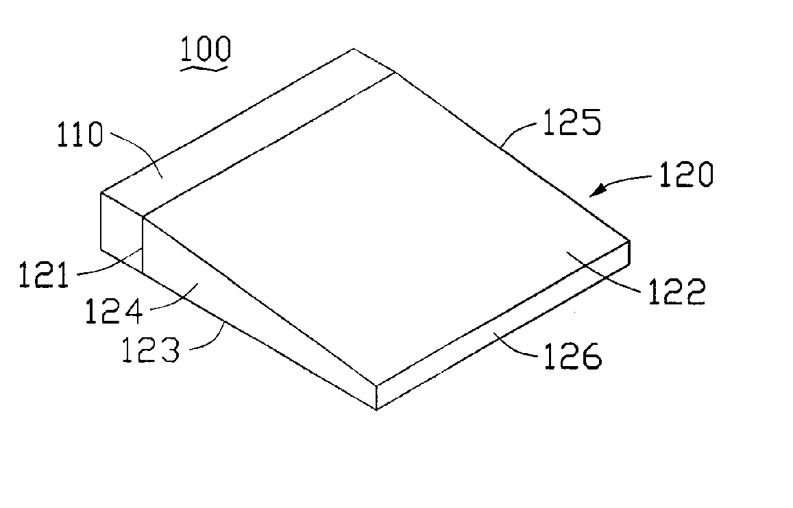
[0028]FIG. 3 shows a backlight device 100 in accordance with a The backlight device 100 includes a light source 110 and a light guiding plate 120. The light source 110 is arranged at a side face of the light guiding plate 120.

[0029] The light guiding plate 120 is generally in a form of a flat or wedge-shaped sheet that includes a light incident surface 121, a light emitting surface 122, a light reflecting surface 123, and reflecting side surfaces 124, 125, 126, formed, optionally, with reflecting layers thereon. The light incident surface 121 is disposed facing the light source 110 and is adapted / configured for receiving light emitted therefrom. The light reflecting surface 123 is configured for reflecting the light incoming through the light incident surface 121. The light emitting surface 122 is opposite to the light reflecting surface 123 and is adapted for facilitating emission of light from the light guiding plate 120, including the exit of the reflected light. In the illustra...

second embodiment

[0041]FIG. 6 illustrates an alternative light source 310 in accordance with a The light source 310 includes a cathode 311; a field emission portion 302 formed on the cathode 311; and a light-permeable anode 317 arranged opposite from the cathode 311. The anode 117 is formed on a transparent substrate 318. At least one fluorescent layer 316 is formed on the anode 317 and faces the cathode 311.

[0042] The field emission portion 302 includes a plurality of supporters 314 formed on the cathode 311; and a plurality of field emitters 315 formed on the supporters 314.

[0043] Referring to FIG. 7, a single exemplary supporter 314 and a corresponding field emitter 315 are described as follows. The supporter 314 of the second embodiment is similar to the isolating post 114 of the first embodiment, except that the supporter 314 includes a conductive core portion 3143 and an insulating enclosing portion 3141 surrounding the core portion 3143 therein. Further, the conductive core portion 3143 int...

third embodiment

[0045] Referring to FIG. 8, a backlight device 300 in accordance with a third embodiment is shown. The backlight device 300 mainly includes a light guide plate 320 and the light source 310.

[0046] The light guide plate 320 is a substantial cuboid (i.e., a rectangular parallelepiped) having a notched corner portion. A surface of the notched corner portion is utilized as a light incident surface 328 of the light guide plate 320. The light guide plate 320 further includes a light emitting surface 322 perpendicularly adjoining the light incident surface 328, a light reflecting surface opposite to the light emitting surface 322, and four side surfaces 323, 324, 327, and 326. The side surfaces 323, 324, 327, 326, and the light reflecting surface can be configured to be reflective surfaces by coating reflective films thereon, respectively. The light incident surface 328 is slanted / angled at a predetermined degree with respect to two side surfaces 324, 327. The predetermined degree is prefer...


PUM


Abstract

A backlight device (100) includes a light source (110) and a light guiding plate (120). The light source includes a cathode (111); a nucleation layer (112) formed on the cathode; a field emission portion (102) formed on the nucleation layer; and a light-permeable anode (117) arranged over the cathode. The field emission portion includes an isolating layer (113) formed on the cathode; a plurality of isolating posts (114) disposed on the isolating layer; and a plurality of field emitters (115) located on the respective isolating posts. The light guiding plate includes an incident surface (121) facing the light-permeable anode and adapted for receiving light emitted from the light source.

Description

CROSS-REFERENCES TO RELATED APPLICATION [0001] This application is related to a first copending U.S. utility patent application Ser. No., entitled “A BACKLIGHT DEVICE USING A FIELD EMISSION LIGHT SOURCE” filed on [Date], a second copending U.S. utility patent application Ser. No., entitled “FIELD EMISSION LIGHT SOURCE” filed on [Date], a third copending U.S. utility patent application Ser. No., entitled “FIELD EMISSION LIGHT SOURCE” filed on [Date], which is entirely incorporated herein by reference.FIELD OF THE INVENTION [0002] The present invention relates to liquid crystal display (LCD) technology and, more particularly, to a backlight device employing a field emission light source. DESCRIPTION OF RELATED ART [0003] In general, an LCD apparatus has many advantages over a CRT (cathode ray tube) display apparatus, especially in respect to weight and size. The advantage of an LCD derives from its use of liquid crystal for providing images. The liquid crystal is controlled by an elec...

Claims


Application Information

Patent Timeline
IPC IPC(8): H01J63/04H01J1/62
CPCG02B6/0038G02B6/0046G02B6/0066G02F1/133615H01J9/025H01J63/02H01J63/04H01J63/06
Inventor CHEN, GA-LANE
Owner HON HAI PRECISION IND CO LTD
Why Eureka
Try Eureka