
Systems, methods and apparatus for inducing electromagnetic mutual inductance in magnetic coils to reduce inhomogeneity in a magnetic field of the magnetic coils

Active Publication Date: 2006-09-07
GENERAL ELECTRIC CO
View PDF4 Cites 8 Cited by
  • Summary
  • Abstract
  • Description
  • Claims
  • Application Information

AI Technical Summary

Benefits of technology

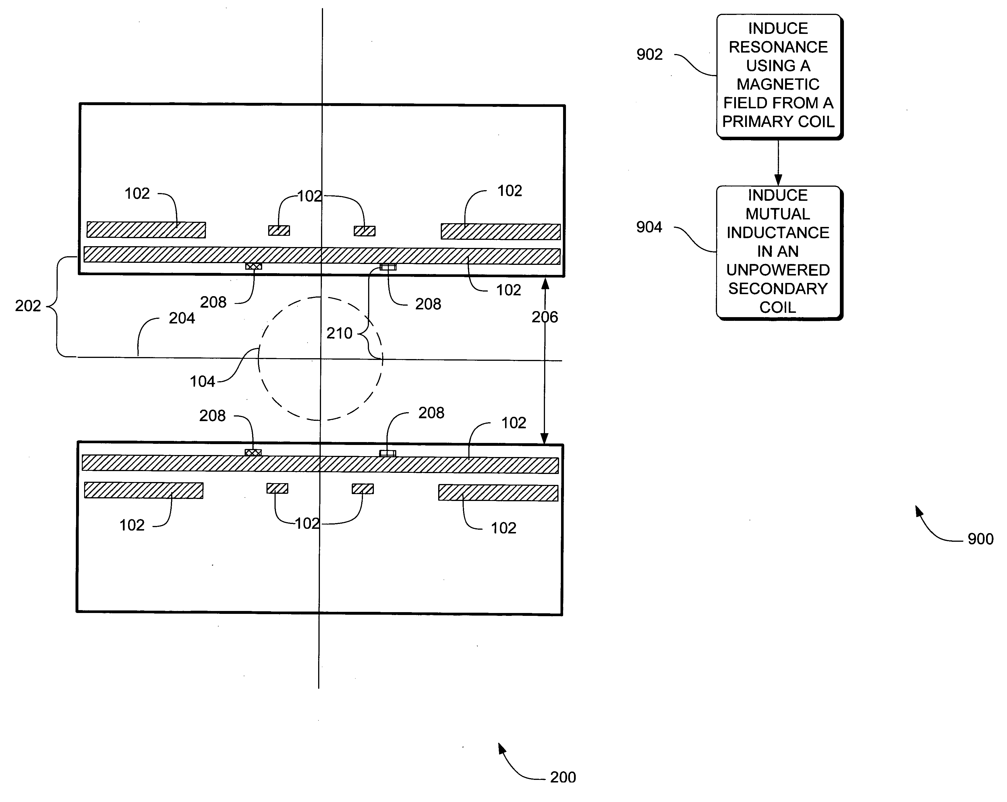
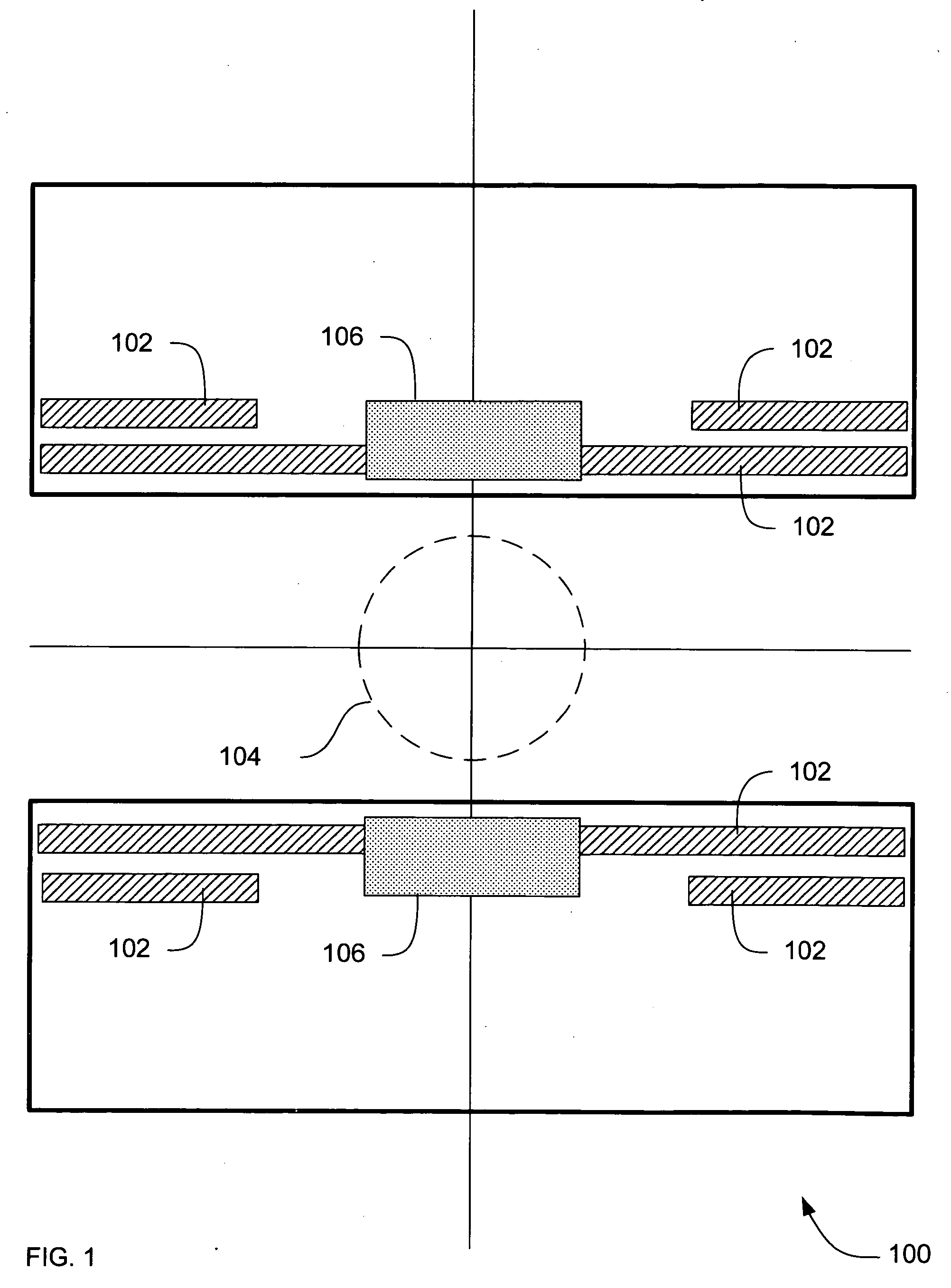
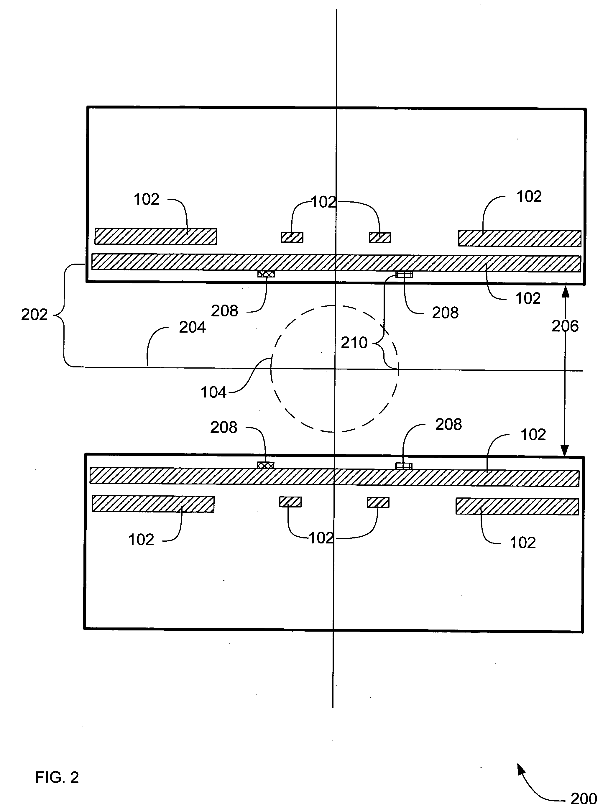
[0012] In one aspect, an apparatus includes a primary coil operable to generate the magnetic field and a secondary coil that is positioned in relation to the primary coil to induce electromagnetic mutual inductance with the primary coil to the extent that homogeneity in the magnetic field is increased. Without large amounts of magnetic material or significant complexity in the manufacturing, installation and maintenance of the apparatus, inhomogeneity in the magnetic field is reduced by more than mere fine adjustments in the magnetic field.

Problems solved by technology

Configuring a plurality of coils which collectively produce an extremely uniform field is possible, but unfortunately when magnets are constructed, manufacturing tolerances introduce minor perturbations in the actual coil dimensions, causing a reduction in the actual homogeneity.
However, the extent of capability of room temperature shims to effect homogeneity of the magnetic field is limited.
Although superconducting correction coils are probably the most effective conventional means to improve homogeneity of the magnetic field, superconducting correction coils are also by far the most complex to manufacture.
Superconducting correction coils are also susceptible to experiencing large induced currents during a magnet quench.
Also, being located within a helium vessel, the superconducting correction coils are totally inaccessible and very difficult to repair.
Furthermore, setting currents of the superconducting correction coils requires a high level of technician skill and sophisticated equipment.
However, very large amounts of magnetic material are required to quell large homogeneity perturbations and the large mass of ferrous material can affect performance because of temperature effects of passive shims and white pixels that the passive shims cause.
Furthermore, the magnetization of passive shims often makes installation of the passive shims difficult while the primary magnet is energized.
Passive shims are also problematic because the passive shims occupy space within the bore of the MRI system and the passive shims require high tray insertion forces.

Method used


Image

  • Systems, methods and apparatus for inducing electromagnetic mutual inductance in magnetic coils to reduce inhomogeneity in a magnetic field of the magnetic coils
  • Systems, methods and apparatus for inducing electromagnetic mutual inductance in magnetic coils to reduce inhomogeneity in a magnetic field of the magnetic coils
  • Systems, methods and apparatus for inducing electromagnetic mutual inductance in magnetic coils to reduce inhomogeneity in a magnetic field of the magnetic coils

Examples


Embodiment Construction

[0029] In the following detailed description, reference is made to the accompanying drawings that form a part hereof, and in which is shown by way of illustration specific embodiments which may be practiced. These embodiments are described in sufficient detail to enable those skilled in the art to practice the embodiments, and it is to be understood that other embodiments may be utilized and that logical, mechanical, electrical and other changes may be made without departing from the scope of the embodiments. The following detailed description is, therefore, not to be taken in a limiting sense.

[0030] The detailed description is divided into four sections. In the first section, a system level overview is described. In the second section, apparatus of embodiments are described. In the third section, a method of an embodiment is described. Finally, in the fourth section, a conclusion of the detailed description is provided.

System Level Overview

[0031]FIG. 1 is a cross section block d...


PUM


Abstract

Systems, methods and apparatus are provided through which inhomogeneity in a magnetic field is reduced by invoking electromagnetic mutual inductance between a main coil and another coil.

Description

FIELD OF THE INVENTION [0001] This invention relates generally to generating magnetic fields, and more particularly to modifying generated magnetic fields. BACKGROUND OF THE INVENTION [0002] Magnetic resonance imaging (MRI) systems use a magnetic field to sense the structure of an object. The structure creates perturbations and variations in the strength of the magnetic field. The perturbations and variations in the strength of the magnetic field are sensed and interpreted to provide an image of the structure of the object. In many MRI systems, the magnetic field is generated by a superconducting magnet to provide a strong magnetic field. [0003] For a preponderance of superconducting MRI systems, it is necessary to obtain an extremely uniform field in a defined volume because interpreting of the magnetic field assumes a magnetic field of uniform strength. Uniformity is also known as homogeneity. Configuring a plurality of coils which collectively produce an extremely uniform field i...

Claims


Application Information

Patent Timeline
IPC IPC(8): G01V3/00
CPCG01R33/387G01R33/3875H01F7/20
Inventor HOLLIS, TIMOTHY JAMES
Owner GENERAL ELECTRIC CO
Learn More