Ultra low power oscillator

Inactive Publication Date: 2006-09-07
SAMSUNG ELECTRONICS CO LTD
View PDF5 Cites 4 Cited by
  • Summary
  • Abstract
  • Description
  • Claims
  • Application Information

AI Technical Summary

Benefits of technology

[0011] The present invention provides an ultra low power oscillator that can reduce power consumption by limiting current supplied to respective inverters using a current limit circuit.

Problems solved by technology

Accordingly, power consumption greatly increases, and thus the conventional oscillator cannot be used for an ultra low power system that requires the whole current consumption within the range of several μA.
Also, in the conventional oscillator, it is difficult to design output clock signals with waveforms symmetrical to each other based on a center level.

Method used


Image

  • Ultra low power oscillator
  • Ultra low power oscillator
  • Ultra low power oscillator

Examples


Embodiment Construction

[0028] Certain exemplary embodiments of the present invention will be described in greater detail with reference to the accompanying drawings.

[0029] In the following description, same drawing reference numerals are used for the same elements even in different drawings. The matters defined in the description such as a detailed construction and elements are provided to assist in a comprehensive understanding of the invention. Thus, it is apparent that the present invention can be carried out without those defined matters. Also, well-known functions or constructions are not described in detail since they would obscure the invention with unnecessary detail.

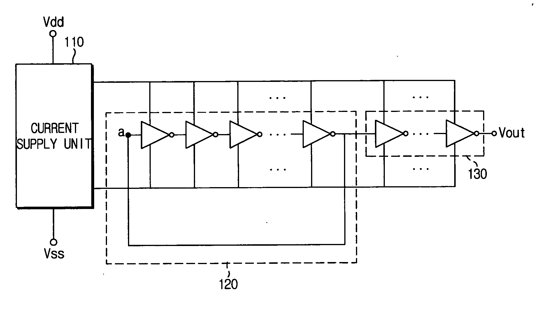
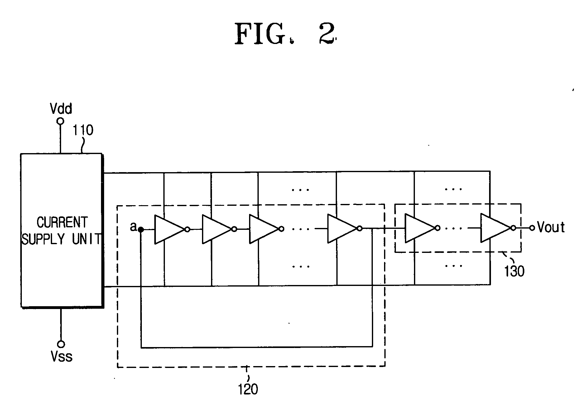
[0030]FIG. 2 is a block diagram illustrating the construction of an ultra low power oscillator according to an exemplary embodiment of the present invention. Referring to FIG. 2, the ultra low power oscillator according to the embodiment of the present invention includes a current supply unit 110, an oscillation unit 120 and an outp...


PUM

PropertyMeasurementUnit
Poweraaaaaaaaaa
Currentaaaaaaaaaa
Frequencyaaaaaaaaaa

Abstract

An ultra low power oscillator includes a current supply unit converting current supplied from an external bias power source into first and second low currents of predetermined amounts, and an oscillation unit oscillating and creating a predetermined frequency signal if the first and second low currents are supplied from the current supply unit. The oscillation unit includes a plurality of inverters connected in series, and the current supply unit includes a current limit circuit composed of NMOS and PMOS transistors connected to the respective inverters. The current flowing when the transistors in the respective inverters are simultaneously turned on is limited, and thus the power consumption can be reduced.

Description

[0001] This application claims benefit under 35 U.S.C. § 119 from Korean Patent Application No. 2005-14643 filed on Feb. 22, 2005 in the Korean Intellectual Property Office, the disclosure of which is incorporated herein by reference. BACKGROUND OF THE INVENTION [0002] 1. Field of the Invention [0003] The present invention relates to an ultra low power oscillator, and more particularly, to an ultra low power oscillator that supplies a low current using a current limit circuit to reduce power consumption. [0004] 2. Description of the Related Art [0005] An oscillator is a device that generates an oscillating frequency signal of a predetermined level for use in a semiconductor chip. Generally, the oscillator can be implemented using a plurality of inverters. [0006]FIG. 1 is a circuit diagram illustrating the construction of a conventional oscillator. Referring to FIG. 1, the conventional oscillator includes an oscillation unit 10 composed of a plurality of inverters 11, 12 and 13, and ...

Claims


Application Information

Patent Timeline
IPC IPC(8): H03K3/03
CPCH03K3/012H03K3/0315B32B19/045B32B37/1009B32B2037/1072B32B2307/51B32B2307/726B32B2309/02B32B2309/12B32B2471/04
Inventor KU, JA-NAMKIM, CHUNG-WOULMIN, YOUNG-HOONSONG, IL-JONGLEE, DONG-HYUN
Owner SAMSUNG ELECTRONICS CO LTD
Why Eureka
Try Eureka