
Resolution adjustment for miniature camera

Active Publication Date: 2006-09-07
DIGITALPTICS MEMS
View PDF15 Cites 12 Cited by
  • Summary
  • Abstract
  • Description
  • Claims
  • Application Information

AI Technical Summary

Benefits of technology

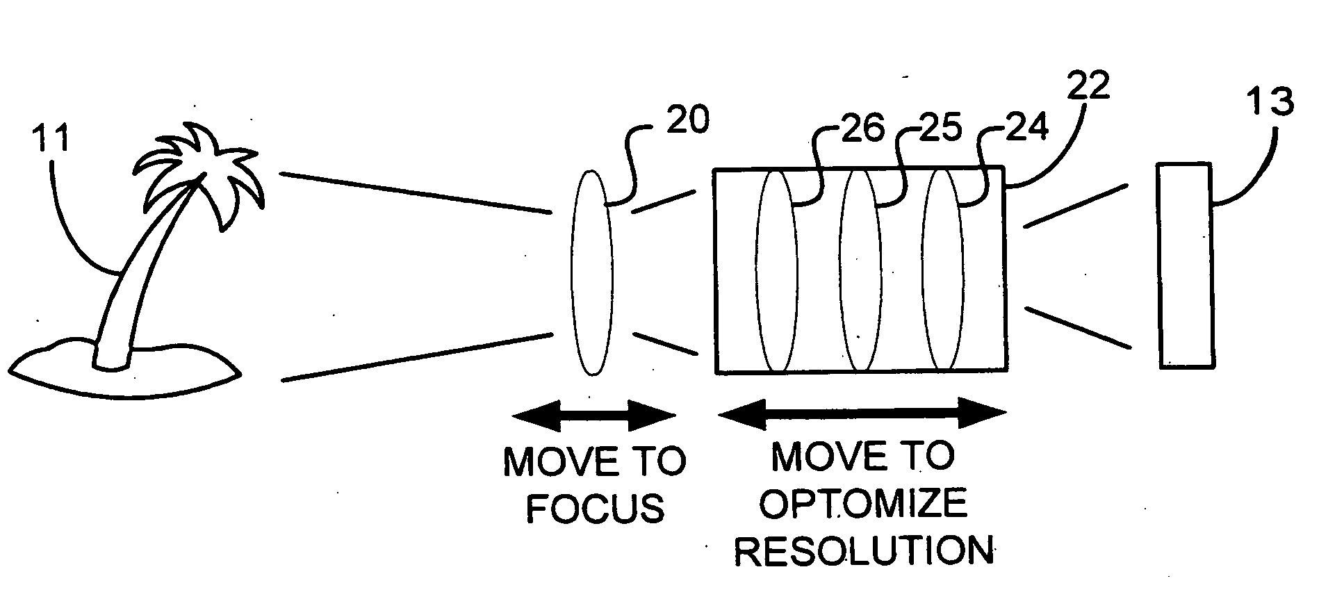
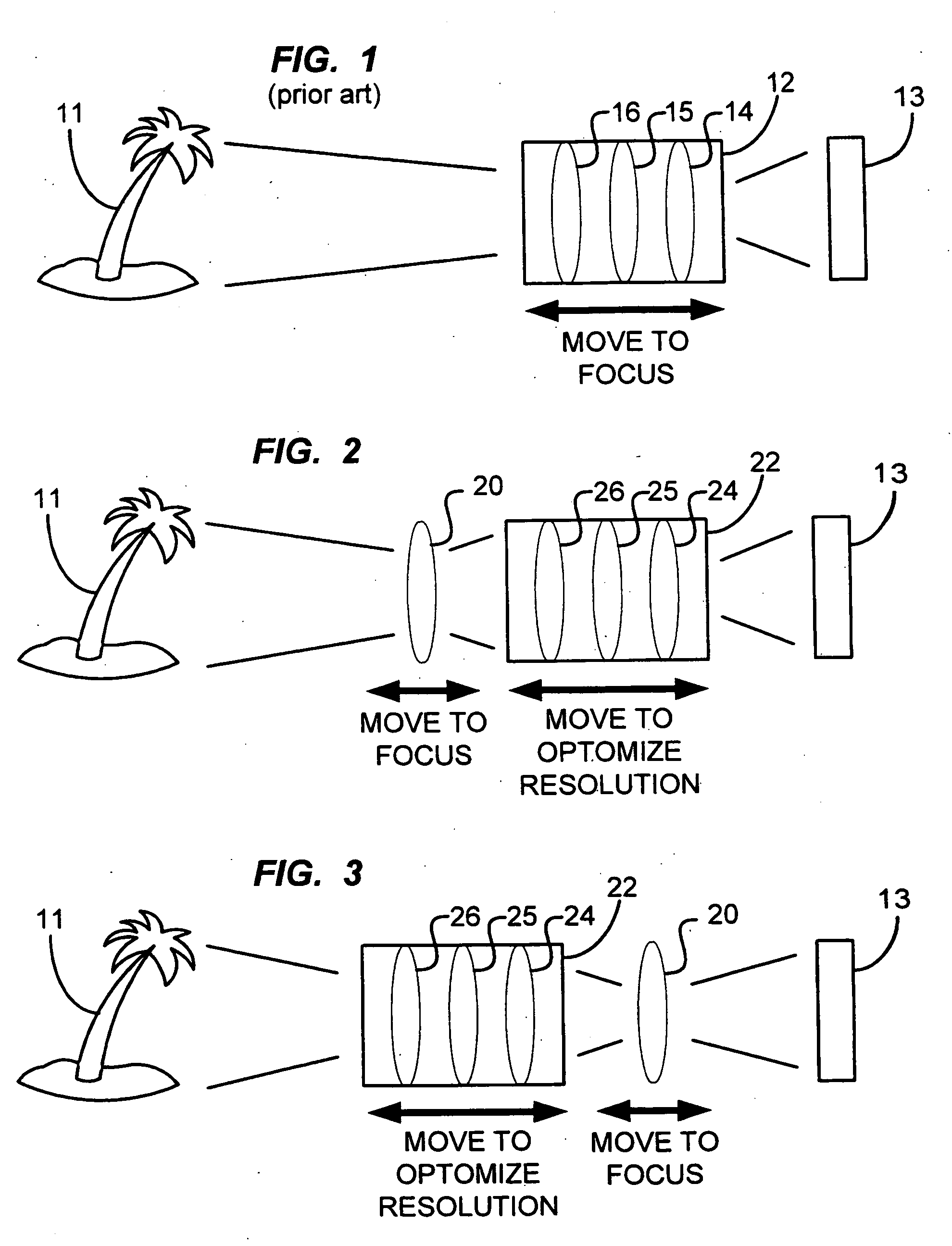
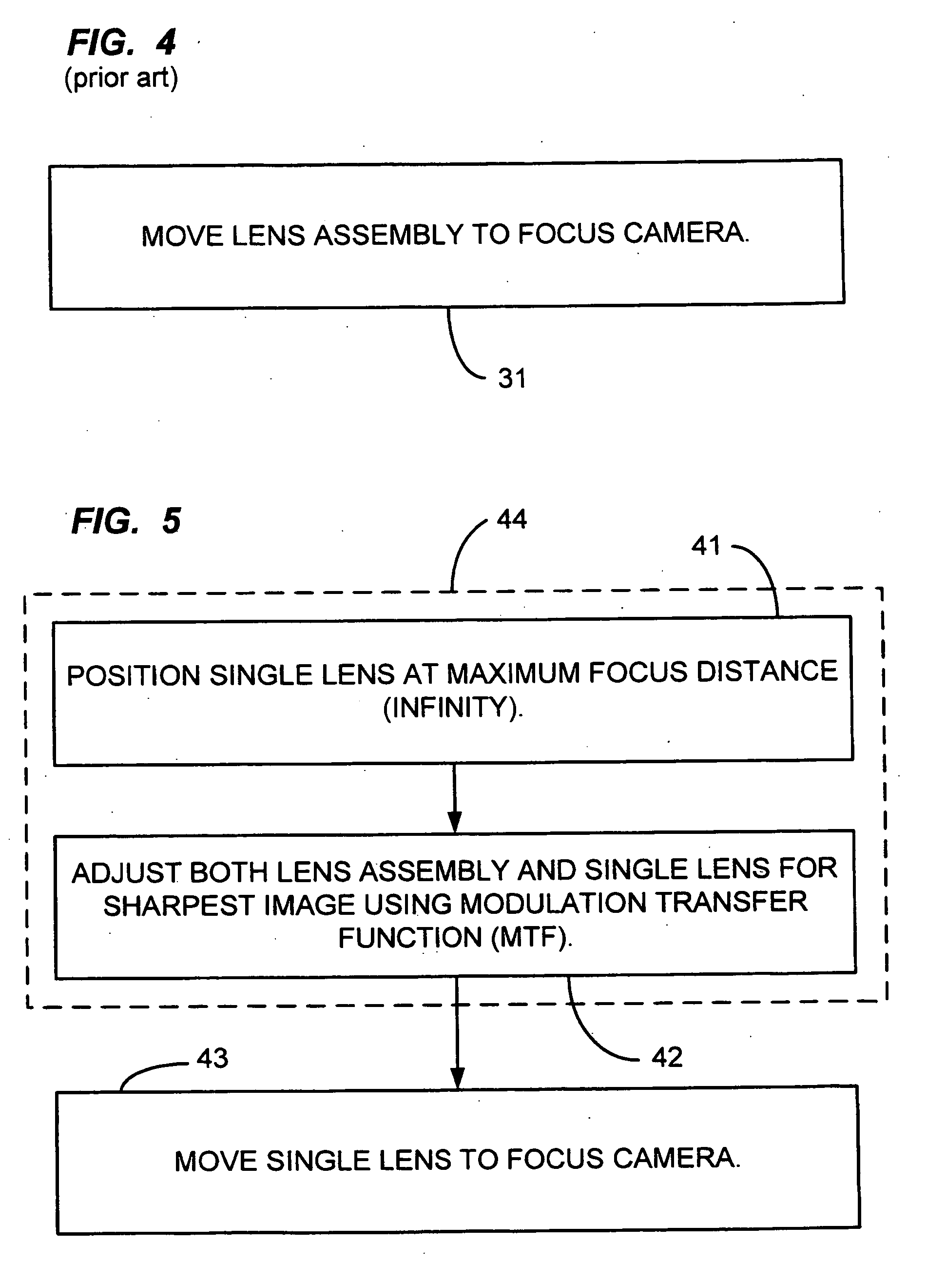
[0006] A method and system for enhancing resolution of a camera are disclosed. The method and system facilitate the production of a miniature camera suitable for use in cellular telephones and the like, wherein the camera has enhanced resolution. According to one aspect of the present invention, the method comprises placing a single lens at a predetermined position and then adjusting the position of a lens assembly so as to enhance resolution.
[0007] More particularly, the single lens can be placed at a position of maximum focus distance, e.g., at a position for focus at infinity. The lens assembly can then be adjusted so as to provide the best focus achievable, as measured by a modulation transfer function (MTF).
[0012] Thus, one or more embodiments of the present invention provide for the enhancement of resolution. Resolution enhancement is facilitated while permitting the subsequent focusing of the camera by moving only a single lens, or at least while leaving one or more lenses stationary. Focusing can alternatively be accomplished by moving more than one lens, such as by moving two, three, or more lenses. Focusing by moving only a single lens reduces the inertia associated with the moving part, thus permitting faster and more accurate focusing.

Problems solved by technology

However, such stopping down severely limits the camera's use in low light conditions.
However, movable optics suffer from inherent disadvantages.
For example, the resolution provided by movable optics can be less than optimal, unless the optics are properly adjusted.

Method used


Image

  • Resolution adjustment for miniature camera
  • Resolution adjustment for miniature camera
  • Resolution adjustment for miniature camera

Examples


first embodiment

[0066]FIG. 8 is a table of exemplary lens parameters associated with the lenses of FIG. 8, according to the present invention.

[0067]FIG. 9 is a table of exemplary nominal values for parameters associated with the aspheric lens of FIG. 8, according to the first embodiment of the present invention. As those skilled in the art will appreciate, an even aspheric surface is defined as:

Z=(y2 / r) / [1+{1−(K+1)(y / r)2}1 / 2]+A4y4+A6y6+A8y8+A10y10+A12y12+A14y14

[0068] where z represents the coordinate in the direction of the optical axis, r is the curvature radius of the surface, y represents the radial distance from the optical axis, K represents a conic coefficient, and A4, A6, A8, A10, A12, and A14 represent spherical coefficients. The two even aspheric surfaces are defined in the tables of FIGS. 9 and 19.

[0069] This formula applies to the tables of both FIG. 9 and FIG. 19.

[0070]FIG. 10 is a chart showing the polychromatic diffraction modulation transfer function (MTF) of the first embodiment...

second embodiment

[0078]FIG. 18 is a table of exemplary lens parameters associated with the lenses of FIG. 8, according to the present invention.

[0079] In the table of FIG. 18, D7 can be from approximately 1.01 to approximately 1.31 millimeter and D9 can be from approximately 0.593 to approximately 0.293 millimeter for an object at a distance between 10 centimeters and infinity with respect to the first surface of lens assembly 702.

[0080] The field of view is 57.6 degrees. The F number is between 2.9 and 3.0 for an object at a distance between 10 centimeters and infinity with respect to the first surface of lens assembly 702.

[0081]FIG. 19 is a table of exemplary nominal values for parameters associated with the aspheric lens of FIG. 8, according to the second embodiment of the present invention.

[0082]FIG. 20 is a chart showing the polychromatic diffraction modulation transfer function (MTF) of the second embodiment of the present invention, for an object at infinity. The MTF at spatial frequency o...


PUM


Abstract

A method and system for enhancing the resolution of a camera are disclosed. For example, a single lens can be placed at a predetermined position and the position of a lens assembly can be adjusted so as to enhance the resolution of the camera. The single lens can then be moved so as to effect focusing of the camera while the position of the lens assembly tends to maintain enhanced resolution thereof.

Description

PRIORITY CLAIM [0001] This patent application claims the benefit of the priority date of U.S. provisional patent application Ser. No. 60 / 657,261, filed on Feb. 28, 2005 and entitled AUTOFOCUS CAMERA (docket No. M-15826-V1 US) and priority date of U.S. provisional patent application Ser. No. 60 / 697,476, filed on Jul. 7, 2005 and entitled RESOLUTION ADJUSTMENT FOR MINIATURE CAMERA (docket no. M-15923-V1 US) pursuant to 35 USC 119. The entire contents of these provisional patent applications are hereby expressly incorporated by reference.TECHNICAL FIELD [0002] The present invention relates generally to optics. The present invention relates more particularly to a method and system for adjusting the resolution of a miniature camera, such as an autofocus camera suitable for use in cellular telephones and the like. BACKGROUND [0003] Miniature cameras are well known. Miniature cameras are widely used in contemporary cellular telephones. They are also used in other devices, such as laptop co...

Claims


Application Information

Patent Timeline
IPC IPC(8): G03B13/18
CPCG03B3/02G03B13/36G03B29/00H04N5/23212H04N23/675
Inventor XU, JINGGUTIERREZ, ROMAN C.TANG, TONY K.
Owner DIGITALPTICS MEMS
Learn More