Method for Depositing Pavement Rejuvenation Material into a Layer of Aggregate

a rejuvenation material and aggregate technology, applied in the direction of roads, building materials handling, construction, etc., can solve the problems of affecting the overall efficiency of the milling process, and requiring frequent replacement, so as to increase the surface energy of aggregate coated

Inactive Publication Date: 2006-09-07
NOVATEK IP
View PDF35 Cites 11 Cited by
  • Summary
  • Abstract
  • Description
  • Claims
  • Application Information

AI Technical Summary

Benefits of technology

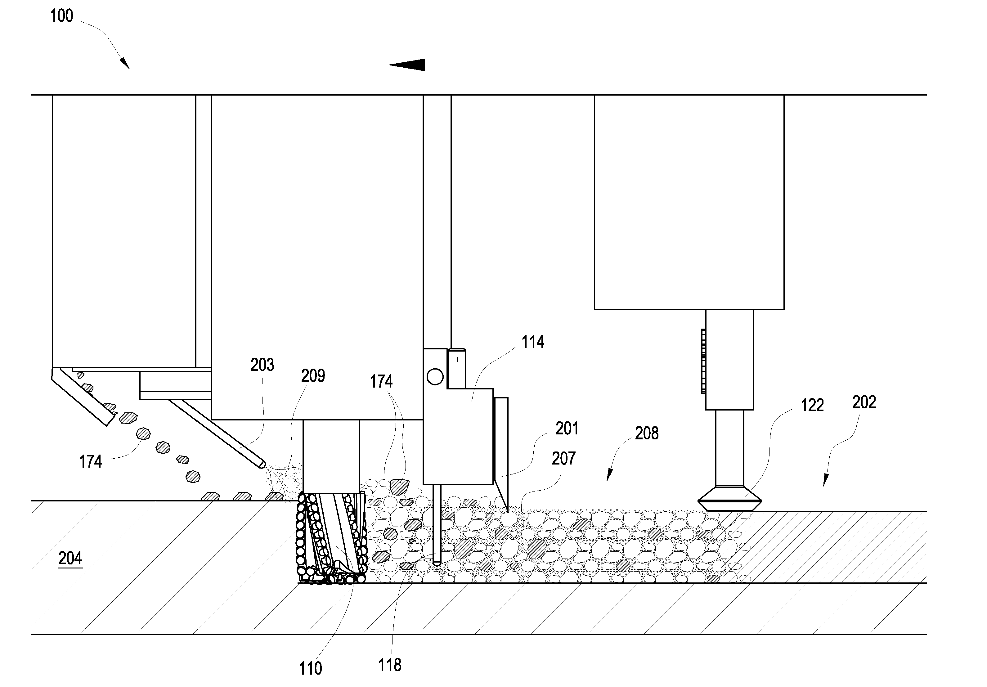
[0012] In some embodiments, it may be desirable to have a sprayer attached to the vehicle which is adapted to spray rejuvenation material into the surface of the layer. This may increase the surface energy of aggregate coated with the rejuvenation material. In some embodiments the sprayed rejuvenation material under goes a foaming process similar to the rejuvenation material traveling through the channel, although the sprayed material may or may not be foamed. The channels may be adapted to vibrate, rotate, shake, move, or oscillate which may help spread rejuvenation material throughout the layer.
[0013] In some embodiments the opening of the channel is protected by a superhard material. This may be beneficial in embodiments where the channel contacts a second layer underneath the layer of aggregate. Preferably, the rejuvenation material is deposited on the second layer and foams up into the layer of pavement aggregate. Since the rejuvenation material is deposited on the second layer it will bond the two layers together.

Problems solved by technology

Due to the abrasive nature of pavement, the cutting teeth traditionally wear out quickly and require frequent replacement.
The replacement process may create significant downtime and hinder the overall efficiency of the milling process.
One shortcoming of current asphalt milling machines is their failure to capitalize on cutting-edge technology used in other industries, such as the downhole drilling industry.

Method used


Image

  • Method for Depositing Pavement Rejuvenation Material into a Layer of Aggregate
  • Method for Depositing Pavement Rejuvenation Material into a Layer of Aggregate
  • Method for Depositing Pavement Rejuvenation Material into a Layer of Aggregate

Examples


Embodiment Construction

[0025] Reference throughout this specification to “one embodiment,”“an embodiment,” or similar language means that a particular feature, structure, or characteristic described in connection with the embodiment is included in at least one embodiment in accordance with the present invention. Thus, use of the phrases “in one embodiment,”“in an embodiment,” and similar language throughout this specification may, but does not necessarily, all refer to the same embodiment.

[0026] Furthermore, the present invention may be embodied in other specific forms without departing from its spirit or essential characteristics. The described embodiments are to be considered in all respects only as illustrative and not restrictive. The scope of the invention is, therefore, indicated by the appended claims rather than by the foregoing description. All changes that come within the meaning and range of equivalency of the claims are to be embraced within their scope.

[0027] In the following description, n...


PUM


Abstract

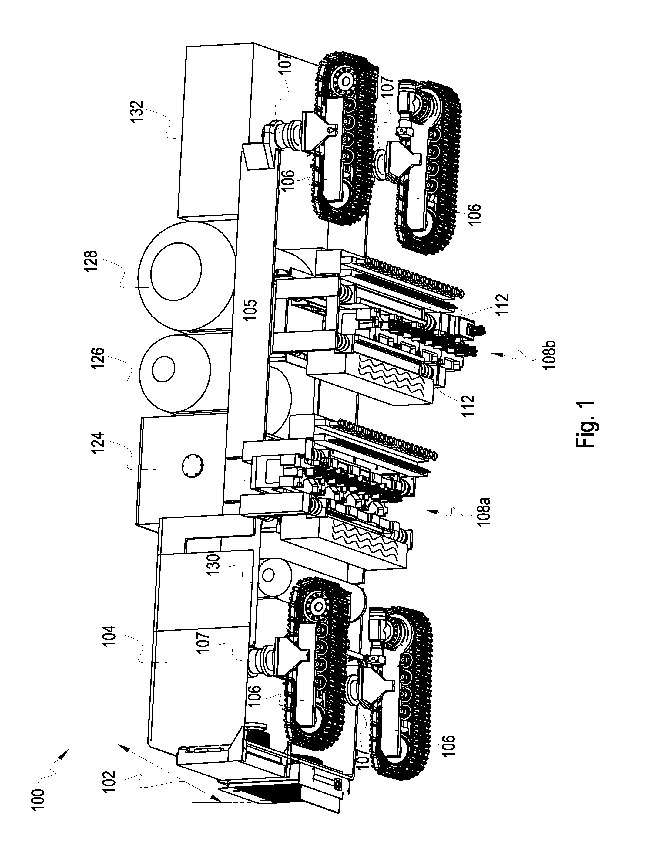
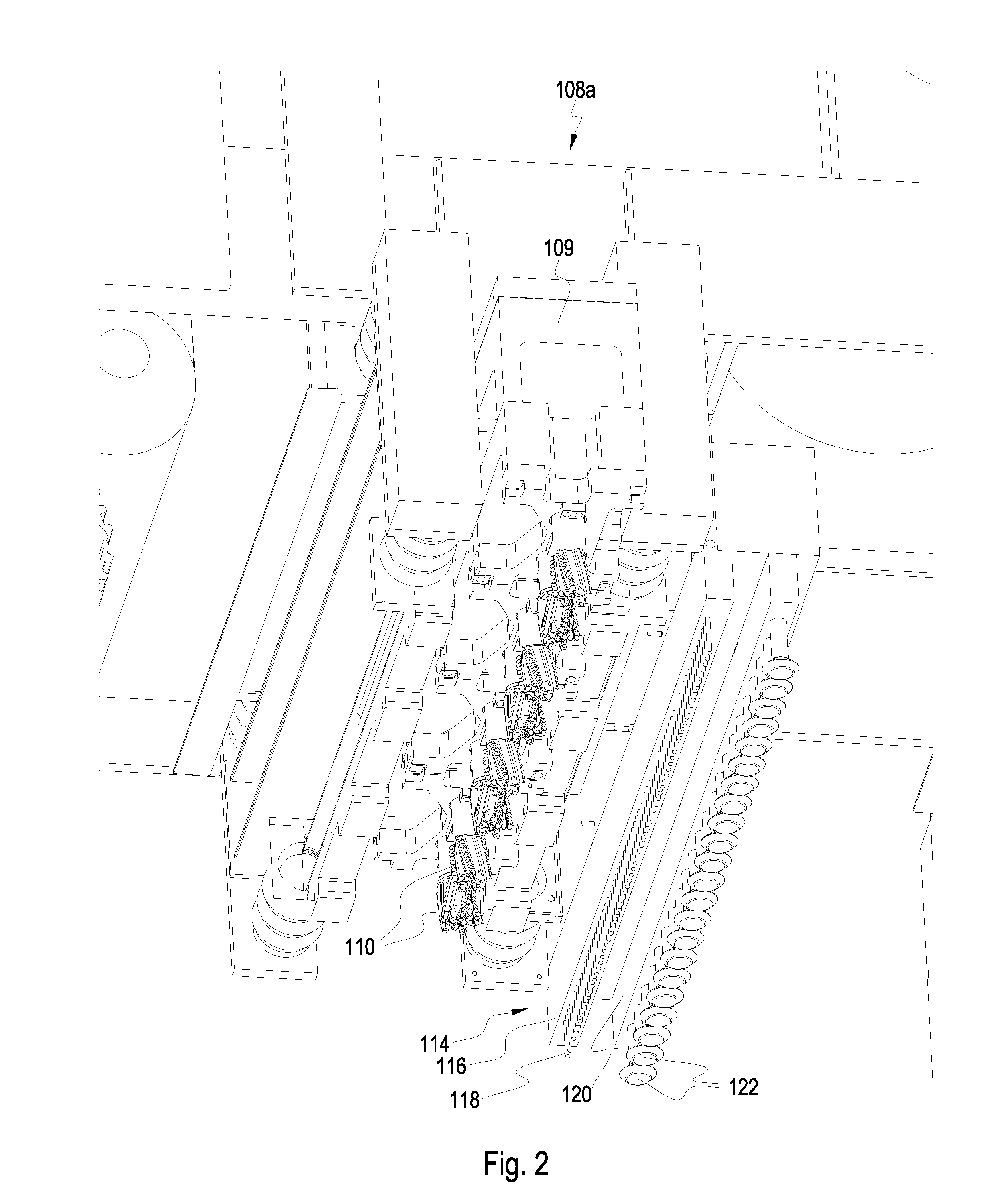
In one aspect of the invention a method includes the steps of providing a channel attached to a vehicle adapted to transverse an area, the channel being in communication with at least one supply of pavement rejuvenation material, and the area having a layer of pavement aggregate; positioning the channel so that at least a portion of the channel is disposed within the layer; and adding the pavement rejuvenation material into the layer from an opening in the channel positioned below the surface of the layer.

Description

CROSS REFERENCE TO RELATED APPLICATIONS [0001] This application is a continuation-in-part of U.S. patent application Ser. No. 11 / 164,947 which was filed on Dec. 12, 2005 and entitled Apparatus for Depositing Pavement Rejuvenation Materials on a Road Surface. U.S. patent application Ser. No. 11 / 164,947 is a continuation-in-part of U.S. patent application Ser. No. 11 / 163,615 filed on Oct. 25, 2005 and entitled Apparatus, System, and Method for In Situ Pavement Recycling. U.S. patent application Ser. No. 11 / 163,615 is a continuation-in-part of U.S. patent application Ser. No. 11 / 070,411 filed on Mar. 1, 2005 and entitled Apparatus, System, and Method for Directional Degradation of a Paved Surface All of the above mentioned U.S. patent applications are herein incorporated by reference for all that they contain.BACKGROUND OF THE INVENTION [0002] The present invention relates to road reconstruction equipment and, more particularly, to a method for depositing pavement rejuvenation material...

Claims


Application Information

Patent Timeline
Patent Type & Authority Applications(United States)
IPC IPC(8): E01C7/32
CPCE01C23/0885
Inventor HALL, DAVID R.DUKE, TIMOTHY C.DARANGA, CODRINWAHIQUIST, DAVID
Owner NOVATEK IP
Why Eureka
Try Eureka