Polymer Films for Medical Device Coating

Active Publication Date: 2010-09-09
MT ACQUISITION HLDG LLC
View PDF109 Cites 45 Cited by
  • Summary
  • Abstract
  • Description
  • Claims
  • Application Information

AI Technical Summary

Benefits of technology

[0008]A cost-effective, easy to apply polymer-based coatings and coating methods to seal a substrate, where the collection process on the substrate is efficient, the coating produced is conformal, substantially defect-free and uniform, and the composition of the coating can be regulated and controlled is provided herein. The method and coat

Problems solved by technology

Polymer coating such “active” implants has significant technical challenges and limitations which have made polymer coatings relatively unsuccessful as a means of sealing the devices.
For example, one limitation of traditional coating processes in providing a seal is that traditional polymer coating processes (e.g. dip, spray, etc.) all require the use of a solvent-based system.
Exposing the device to a solvent causes problems in the device.
Furthermore, there are inherent challenges with effective drying of solvent-based polymer coatings.
Solvent-less coating processes (e.g. vapor deposition, plasma deposition, dry powder

Method used


Image

  • Polymer Films for Medical Device Coating
  • Polymer Films for Medical Device Coating
  • Polymer Films for Medical Device Coating

Examples


example 1

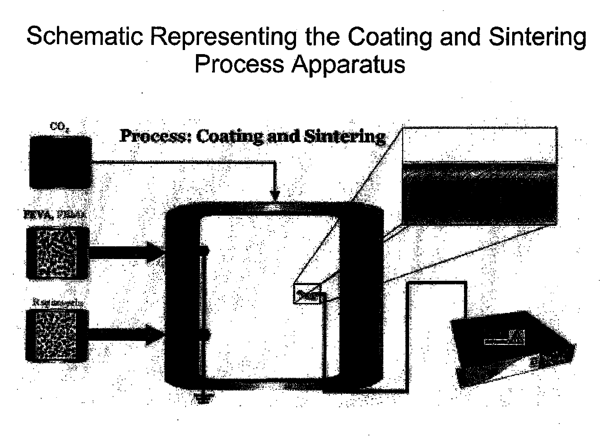
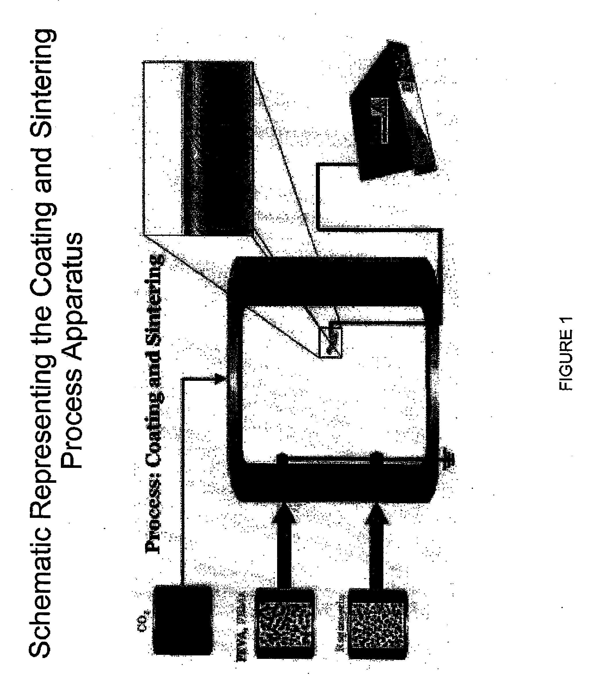
[0103]A biocompatible fluoropolymer or other hydrophobic biocompatible polymer is dissolved in an appropriate supercritical solvent such as carbon dioxide. This solution is maintained in a syringe pump or other pressure vessel and transferred to a spraying vessel that is maintained above the compressed gas's critical pressure and temperature as modified by the solute. The device or other substrate to be coated is held such that it can placed at an electrical potential relative to a nozzle through which the compressed gas solution is to be sprayed (10 kV, for example, with the device held at 5 kV and the nozzle held at −5 kV). The electrical field between the device and the nozzle is designed to be homogenous and constant. The polymer solution is expanded through the restrictor nozzle by electrostatic rapid expansion of a supercritical solution (e-RESS), thereby coating the device with a fine film controllable in both thickness and conformality. Subsequent processing in the gas in it...

example 2

[0104]A biocompatible fluoropolymer or other hydrophobic biocompatible polymer is dissolved in an appropriate supercritical solvent such as carbon dioxide. This solution is maintained in a syringe pump or other pressure vessel and transferred to a spraying vessel that is maintained above the compressed gas's critical pressure and temperature as modified by the solute. The device or other substrate to be coated is held such that it can placed at an electrical potential relative to a nozzle through which the compressed gas solution is to be sprayed (10 kV, for example, with the device held at 5 kV and the nozzle held at −5 kV). The electrical field between the device and the nozzle is designed to be homogenous and constant. The polymer solution is expanded through the restrictor nozzle by electrostatic rapid expansion of a supercritical solution (e-RESS), thereby coating the device with a fine film controllable in both thickness and conformality. Subsequent processing in the gas in it...


PUM

PropertyMeasurementUnit
Temperatureaaaaaaaaaa

Abstract

A method for depositing a coating comprising a polymer and impermeable dispersed solid on a substrate, comprising the following steps: discharging at least one impermeable dispersed solid in dry powder form through a first orifice; discharging at least one polymer in dry powder form through a second orifice; depositing the polymer and/or impermeable dispersed solid particles onto said substrate, wherein an electrical potential is maintained between the substrate and the impermeable dispersed solid and/or polymer particles, thereby forming said coating; and sintering said coating under conditions that do not disrupt the activity and/or function of the substrate. A similar method is provided for depositing a coating comprising a hydrophobic polymer and a water-vapor-trapping material on a substrate.

Description

RELATED APPLICATIONS[0001]This application claims the benefit of priority to U.S. Provisional Patent Application Ser. No. 60 / 940,365 filed May 25, 2007 and U.S. Provisional Patent Application Ser. No. 60 / 979,375 filed Oct. 11, 2007. The disclosure of these applications are incorporated herein by reference in their entirety.BACKGROUND OF THE INVENTION[0002]Medical devices often must be shielded from interacting with body fluids in vivo. For example, for devices that are electrical in nature, for example, such as pacemakers and other “active” implants for sensing, delivery of therapeutics and / or active control of various bodily functions should be protected.[0003]One prevalent method used to provide this protection is to weld the device inside a titanium or other biocompatible metal “can.” Another method to provide the shield necessary to protect a medical device from interaction with bodily fluids in vivo is polymer coating the device. Polymer coating such “active” implants has signi...

Claims


Application Information

Patent Timeline
IPC IPC(8): A61F2/02B05D3/00
CPCA61L27/34A61L31/10A61L2420/02B05D5/08B05D1/04B05D5/083B05D2401/90B05D1/025
Inventor MCCLAIN, JAMESTAYLOR, DOUGLAS
Owner MT ACQUISITION HLDG LLC
Why Eureka
Try Eureka